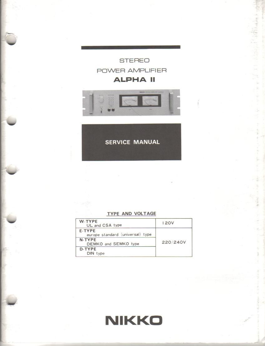
Nikko alpha 2ii pwr sm

This is the 21 pages manual for Nikko alpha 2ii pwr sm.
Read or download the pdf for free. If you want to contribute, please mail your pdfs to info@audioservicemanuals.com.

Page: 1 / 21
left right
Nikko alpha 2ii pwr sm

Extracted text from Nikko alpha 2ii pwr sm (Ocr-read)


Page 2

OPERATING PARTS

POWER

Set the power switch to the ON position and the power
is turned on. The power meters will be illuminated,
indicating that the power is on. The unit will become
active 3 to 6 seconds later because of the employ-
ment of a protective circuit and relay.

SPEAKERS

This switch is used to select speakers connected to the
A and B speaker terminals on the rear panel. When the
switch is set to the AIS position. both speakers con
nected to the A and 8 terminals are operated at the
same time. Speakers may be connected to the A or B
terminals only, if desired. At the OFF position of the
switch, no speakers will operate.

METER RANGE
These two pushbutton switches are used to select the
sensitivity of the power meters in 4 steps.

With the switches ('a' and 'b') in the released position
(11). the power meters will indicate OdB when the
output power of a single tone sign-wave signal reaches
120W (at Sohm load).

By pressing the button switches as shown on the turn
panel, the OdB position on the power meters represents
EDW for -6dB setting, 7.6W for -12dB setting and
0.48W for -24dB setting, respectively.

POWER METER

The power meters indicate the levels of left and rig»!
channel output power in dB. Power levels can be red
directly on the meters with the meter range switches
(3) set in the MB (released) position.