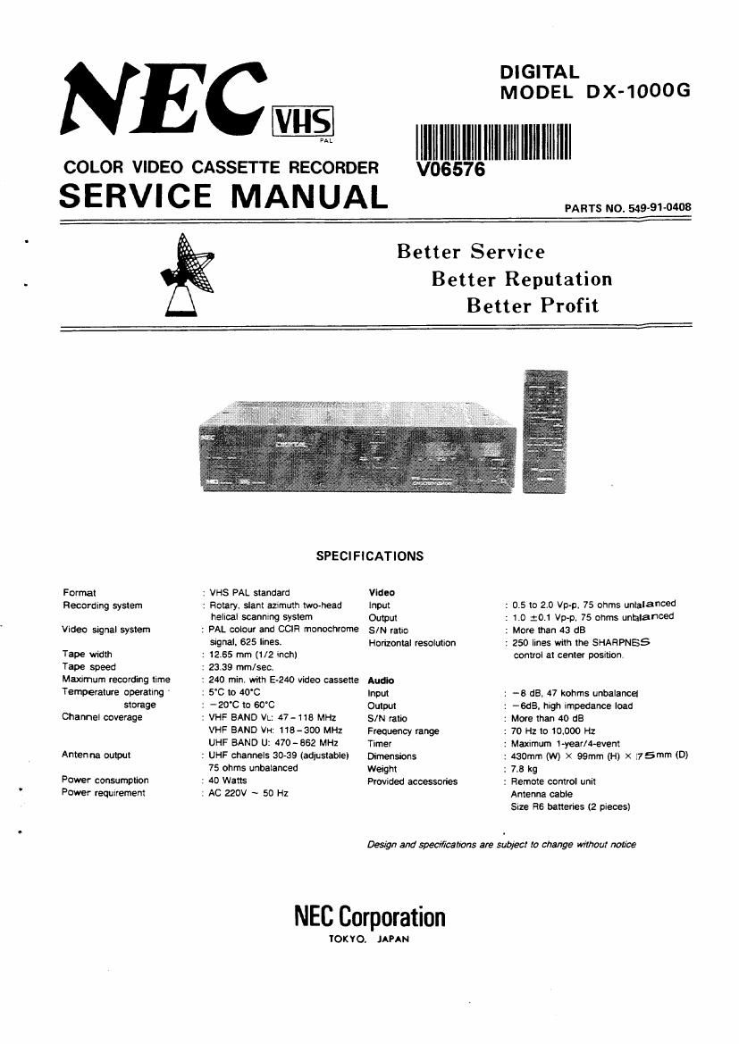
Nec DX 1000 G Service Manual

This is the 128 pages manual for Nec DX 1000 G Service Manual.
Read or download the pdf for free. If you want to contribute, please mail your pdfs to info@audioservicemanuals.com.

Page: 1 / 128
left right
Nec DX 1000 G Service Manual

Extracted text from Nec DX 1000 G Service Manual (Ocr-read)


Page 2

CONTENTS

SECTION 1
Precautions during Servicing ...................... 1-1
Safety Check after Servicing ...................... 1-2
General notes .......
Features ...........
Controls and components . . . . . , . . . .
Antenna connection ......................... 1-9
Video channel setting ......................... 1-10
Camera recording ...... , . . . . , . ,1-11
Before requesting sen/ice ....................... 1-12
SECTION 2
DISASSEMBLV
1. REMOVING THE CASE
1-1. Top cover .......................... 2-1
1-2. Bottomccwer . . .... ....
1-3. Front panel ......................... 2-1
2. CIRCUIT BOARD LOCATIONS
2-1 . Topview ........................... 2-2
2-2. Bottom View ......................... 2-2
3. REMOVING THE CIRCUIT BOARDS
3-1. Sub function circuit board ................. 2-3
3-2. Timer/Function circuit board .............. 2-3
3-3. Preamp circuit board .................... 2-3
3-4. Tuner/1F circuit board. . . . ..... 2-4
3-5. Power/Regulator circuit board . IIIII 2-4
36. Jack terminal circuit board . . . . . ..... 2-5
3-7, Audio circuit board ..................... 2-5
3-8. Digital circuit board .................... 2-6
3-9, VPS Decoder circuit board ................. 2-6
3-10. ON Screen circuit board .................. 2-6
3-11. SIS/V circu it board ..................... 2-7
4. REMOVING THE CASSETTE MECHANISM
4-1. Removing the cassette housing assembly. . . ..... 2-8
4-2. Front oover ...................... 2-8
4-3. Mode sensor circuit board ................. 2-9
44, End sensor circuit board .................. 2-9
4-5. Mechajunction circuit board ............... 2-9
SECTION 3
ADJUSTMENT
I. MECHANICAL ADJUSTMENT
1-1. Servicing jigs and tools ............

1-2. Mechanism assembly ............
1-2-1 Removing the mechanism assembly.
1-2-2 Mechanism parts locations .......

1-3, Before disassembling parts an the chassis ........ 3-4
1-4. Before adjusting the mechanism .............. 3-5
1-5. Sewicing precautions .................... 3-5
15. Replacement of upper rotating dram assembly ..... 3-6
1-7. Replacement of drum assembly .3-6
18. Replacement of ground plate . . . . . . . . .3-7
1-9. Audio/control head ..................... 3-8
1-10. Full erase head ....................... 3-9
1-11. Impedance roller sub assembly .............. 3-9
1-12. intermediate gear ...................... 3-9
1-13. S slant base/TU slant base sub assembly ...... . 3-10
1-14. Entire mode cam assembly ................ 3-11
1-15. Capstan motor ........... . . 3-12
1-16. Pinch arm sub assembly ............ .3-12
1-17. Tension regulation band assembly ...... . 3-12
1-15. Adjusting the tension regulation arm position ..... 3-13
1-19. Supplv reel disk ...................... 313
1-20. Take-up reeldisk . . , . ................ 3-13
1-21, Adjustments when replacing the supply and

takeup reels ....................... 3-14

1-22, Tension regulation arm assembly ............ 3-14
1-23. Measuring and checking the FWD reel torque ..... 3-15
1-24. Measuring and checking the braking torque ...... 3-15
2. CHECKING AND ADJUSTING THE TAPE PATH
2-1. Tape path mechanism 3-16
2 Cecking the tape transport system ........... 3-16
2-3. Adjusting the tape transport system . . ..... 3-17
2-3-1 Adjusting the guide roiler height
(vertical pole height adjustment) ......... 3-17

2-3-2 Adjsting the guide pole and reverse pin heights . 3-17
3. INTERCOMPATIBILITV ADJUSTMENTS

3-1, Checing the FM waverorms ............... 3-20
3-1-1 Check 1 : Checking the playback sWitching point3-2O
3-1-2 Check 2: Checking the FM waveform ...... 3-20
3-1-3 Check 3 ....................... 3-20

3-2. Coarse adjustment of FM waverorms

(preliminary adjustments) ................ 3-21

3-21 Drum entrance side, . . ............ 3-21
3-2-2 Drum exit ........

3-3. Fine adjustment for intercompatibility.

3-4. Ace head adjustment ...........
3-5. Adjusting the CTL position ............... 323
3-6. Final testing and checking ................ 3-23
4. ELECTRICAL ADJUSTMENTS
4-1_ Preparation ........................ 3-24
4-1-1 Required test equipment and iig , ..... 3-24
4-1-2 Alignment tape contents ........... 324
4-2. Servo circuit (SIS/V board) ............... 325
4-3 Audio circuit (AUDIO board) .............. 3-28
4-4. Tuner/IF circuit ...................... 3-29
4-5. VIideo circuit ISIS/V voard) ............... 3-30
4-6. Digitai ........................... 3-35
SECTION 4
DIAGRAMS AND TIMING CHARTS
1 GENERAL BLOCK DIAGRAM ............... . - .4-1
2, BLOCK DIAGRAM
2-1. System control block diagram. . . . . . . . . , , . . . .4-2
2-2. Servo control block diagram ............. 4-3
2-3, Video/Chroma block diagram . , .4-4
2-4. Audio block diagram ...... . , .4-5
2-5, Timer function block diagram, . . .4-6
2-6. Tuner/IF block diagram ............... . . .4-7
2-7. Digital block diagram ................... 4-8
3. TIMING CHART
31 System control timing chart ............. . .4-9
3-2. Assemble record timiming chart 1 . . .4-10
3-34 Assemble record timing chart 2 , . . .4-10
3-4. Drum servo timing chart I ................ 4-11
3-5. Capstan servo timing chart 2 ............... 4-11
4. SCHEMATIC/CIRCUIT BOARD DIAGRAMS
4-1, Frame wiring ....................... 4-12

4-13
11-14
. -.4-15

4-2. Syscon schematic diagram ............. .
4-3. Servo schematic diagram .....
4-4. Video/Chroma schematic diagram .

4-5. Syscon/ServolVideo circuit board . . . , _ 446
4-6. Audio schematic diagram ................ 4-17
4-7t Audio circuit board .................... 4-17
4-8. Preamp schematicdiagram . . . . . . . . . , . . - 4-13
4-9. Pre amo circuit board ................... 4-19
4-10. Timer function schematic diagram . , . .4-20
4-11. Timer function circuit board , . - 4-21

4-12. Sub function schematic diagram ......... - - .4-22