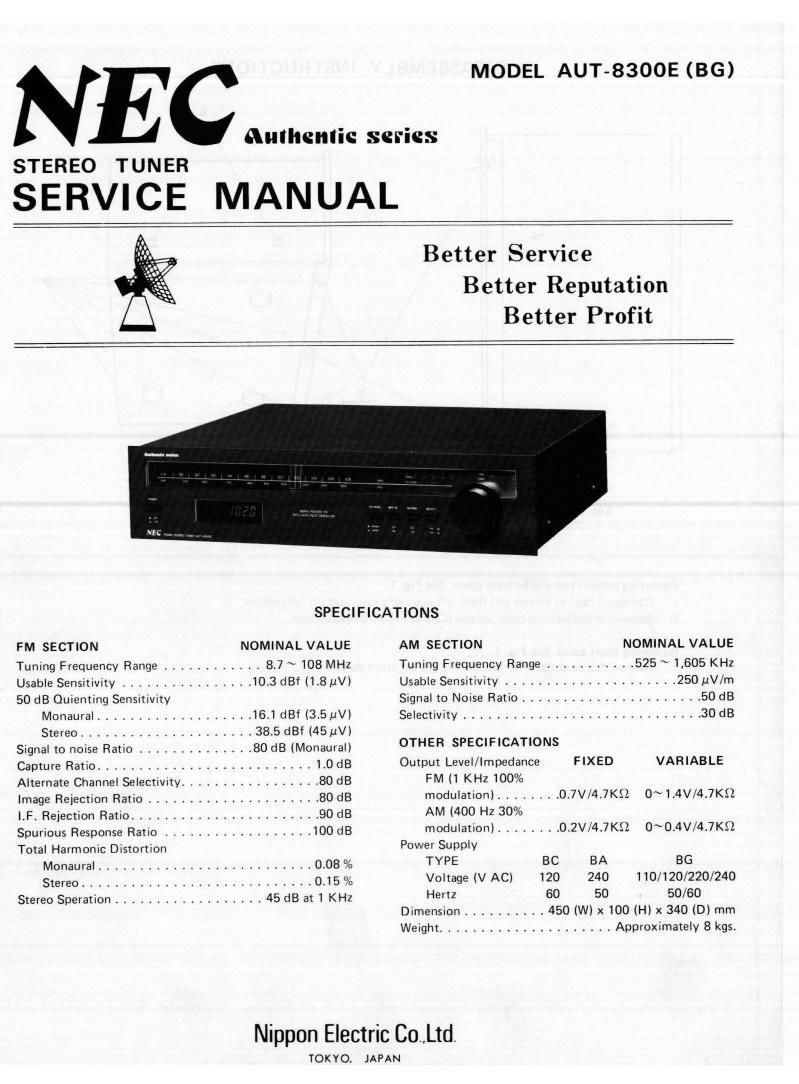
Nec aut 8300e

This is the 14 pages manual for nec aut 8300e.
Read or download the pdf for free. If you want to contribute, please mail your pdfs to info@audioservicemanuals.com.

Page: 1 / 14
left right
nec aut 8300e

Extracted text from nec aut 8300e (Ocr-read)


Page 2

DISASSEMBLY INSTRUCTIONS ALIGNMENT METHOD

A NOTE: In FM alignment, keep P205, 15-16 short-circuited and AFC turned OFF.
-- FM lF Alignment (Fig. 2)
Q (1) Function Switch : "FM

(2) Muting Switch : "OFF"

(3) MPX Filter Switch : "OFF"

(4) FM Mode Switch : AUTO

1. Selectivity Curve Alignment (To use IF Sweep Generator 8: Oscilloscope)

i e C
6 Alignment Point Alignment Method Signal Input Point Signal Output Point

Alignment to be done with weak input signal.

C1069P101-3 P117+>P104 -P(GND)
lFT T1 Save Height max., Symmetric
~r> c» TC5 0Shield case (GND) TP2 0P101- 2 (GND)

B
a»,
o"
.1
Example of Scope Wave Form
FM.Z
Top View Bottom View
Fig. 1 2. 8 curve alignment (Fig. 3) (To use IF Sweep Generator & Oscilloscope)
Alignment Point Alignment Method Signal Input Point Signal Output Point
Removing cabinet top and bottom cover. See Fig. 1. . _ . 9
1. Remove 4 cabinet screws (A) from left and right sides and lift off cabinet. T101 (A) To 3"? at optimal pornt 0f TC5 QShield case (GND) P101 P104 _ 6 (GND)
2. Remove seven bottom cover screws (C) and lift off bottom cover. linearity TP1 9P1D1 - 2 (GND)
Set pointerto O V of volt- . Each end of R119.
Removing front panel. See Fig. 1. T101 (A) meter. No srgnal Refer to Fig. 4.
1. Remove 5 screws (B) from chassis and lift off front panel.

Example of Scope Wave

Fig. 3

R119

E DC voltmeter of center-zero type

q p (for high input impedance)

Fig. 4