Nec AG 100 E Service Manual

This is the 14 pages manual for Nec AG 100 E Service Manual.
Read or download the pdf for free. If you want to contribute, please mail your pdfs to info@audioservicemanuals.com.

Page: 1 / 14
left right
Nec AG 100 E Service Manual

Extracted text from Nec AG 100 E Service Manual (Ocr-read)


Page 1

MODEL
AG-1 00E
TYPE(BC)/(SG)

STEREO GRAPHIC EOUALIZER

SERVICE MANUAL SER. No. 4033

Better Service
Better Reputation
Better Profit

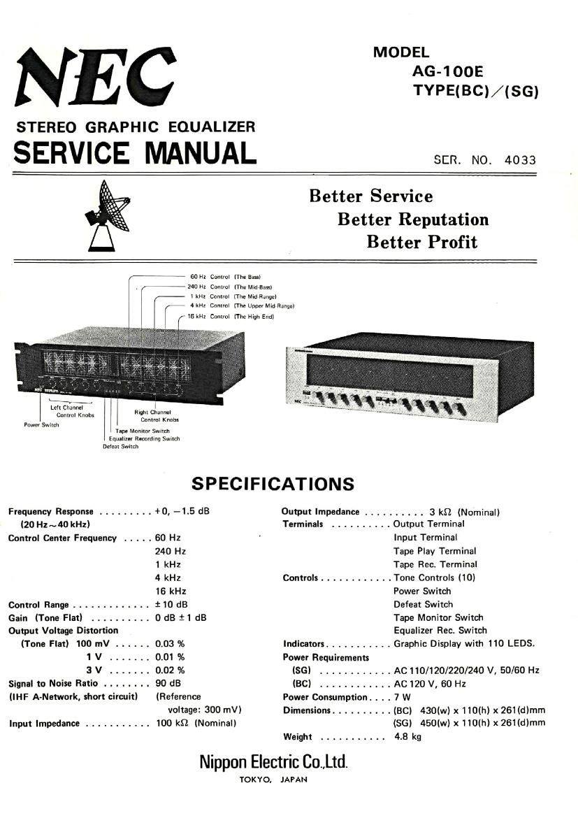
fi 60 HI Control (The 8-)
240 Hz Comm) [The Mld Bil!)
I kHl Control (The Mid Range)
4 kHz Conlml (The Upper Mid Range)

, IS kHz Control (The High End)

H w _ .
Lelt Channel
Control Knobs

l
rwu Channel
Conlml Knobi

Power Switch
hp. Monitor 5mm.

Equanm fiacnrdlng 5mm
Defeat Switch

SPECIFICATIONS

Frequency Response ......... +0. -1.5 (18 Output Impedance .......... 3 k0 (Nominal)
I20 Hz ~40 kHz) Terminals .......... Output Terminal
Control Center Frequency ..... 60 Hz ' Input Terminal
240 Hz Tape Play Terminal
1 kHz Tape Rec. Terminal
4 kHz Controls ............ Tone Controls (10)
16 kHz Power Switch
Control Range ............. i 10 dB Defeat Switch
Gain (Tone Flat) .......... 0 dB 11 dB Tape Monitor Switch
Output Voltage Distortion Equalizer Rec. Switch
(Tone Flat) 100 mV ...... 0.03 % Indicators ........... Graphic Display with 110 LEDS.
1 V ....... 0.01 % Power Requirements
3 V ....... 0.02 % (SG) ............ AC 110/120/220/240 V, 50/60 Hz
Signal to Noise Ratio ........ 90 dB (BC) ............ AC 120 V, 60 Hz
(IHF A-Network, short circuit) (Reference Power Consumption. . . . 7 W
voltage: 300 mV) Dimensions .......... (BC) 430(w) x 110(h) x 261(dlmm
Input Impedance ........... 100 kg (Nominal) (SG) 450(w) x 110(h) x 261(d)mm
Weight ........... 4.8 kg

Nippon Electric Co.,Ltd.

TOK YO. JAPAN

Page 2

DISASSEMBLY INSTRUCTION

(B)

(A)

Figure 1

Removing Cabinet Top. See Figure 1.
Remove four cabinet mounting screws (A) and lift off cabinet top
Note: Before removing cabinet top. be sure to take off two handles and ten knobs.
Removing Front Panel. See Figure 1.
Remove four front panel mounting screws (B) from top and bottom sides then lift off front panel.

TRANSISTOR LEAD CONNECTION

TR101
28C1775
TR102 ,
TR601
2SA872
TRGOZ
E C B
O
TR401 ZSC1096
TR402 25A634
B C E