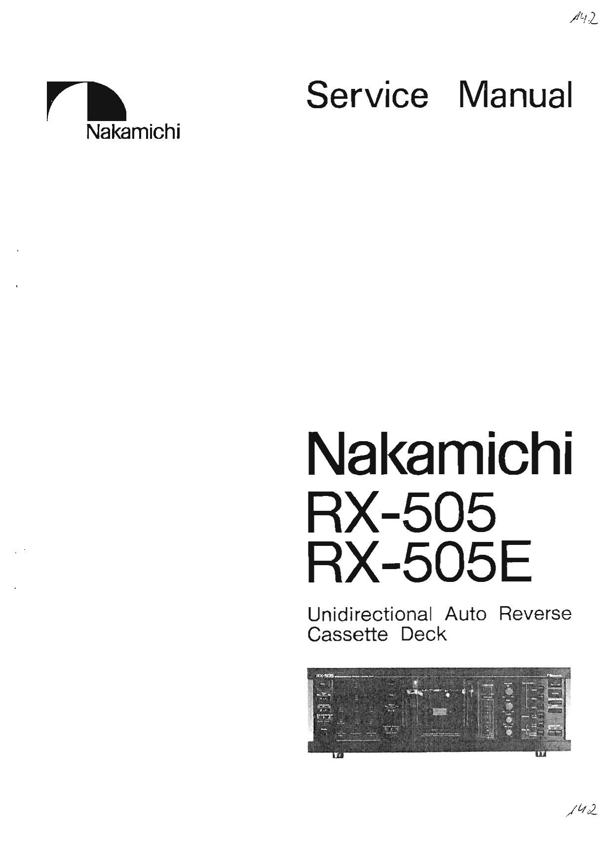
Nakamichi RX 505E Service Manual

This is the 63 pages manual for Nakamichi RX 505E Service Manual.
Read or download the pdf for free. If you want to contribute, please mail your pdfs to info@audioservicemanuals.com.

Page: 1 / 63
left right
Nakamichi RX 505E Service Manual

Extracted text from Nakamichi RX 505E Service Manual (Ocr-read)


Page 2

CONTENTS

1. General ...................................................................... 2
2. Mechanical Adjusianenta .......................................................... 2
2. 1. Preparation for Adjustment ............................................. 2
2, 2. Mechanism Control Cam Adjustment .......................................... 3
2. 3. Reel Motor Speed Adjustment in Play Mode ..................................... 3
2. 4. Record Head and Playback Head Tilt Adjustment .................................. 4
2. 5. Head Base Stroke Adjustment ............................................... 5
2. 6. Erase Head Stroke Adjustment and Tape Guide Height Check .......................... 5
2. 7. Erase Head Height and Tilt Adjustment ........................................ 6
2. 8, Back Tension Adjustment ................................................. 6
2. 9. Playback Head and Record Head Height Adjustment and Azimuth Alignment ............... 7
2. 10. Record Head Stroke Adjustment ............................................. 7
2 11, Tape Travelling Adjustment ................................................ 3
2 1 2. Flywheel Holder Adjustment .............................................. 3
2. 13. Tape Speed Adjustment ................................................... 9
2. 14. Slide Bare Position Adjustment .............................................. 9
2.15 Lubrication ........................................................... 9
3. Parts Location for Electrical Adjustment ................................................ 10
4. Electrical Adjustments and Measurements ............................................... 11
4. 1. Adjustment and Measurement Instructions ...................................... 11
4. 2. Playback hequency Response Adjustment ...................................... 13
4. 3. Dolby NR Circuit Check .................................................. 14
6. Mechanism Au'y and Pam List ...................................................... 15
5. 1. Synthesis ............................................................ 1 5
5. 2. Front Panel Aesy (A01) .................................................. 13
5. 3. Chassis Asa'y (A02) ...................................................... 1'7
5. 4. Front Panel Escutcheon L Assy (801) ......................................... 13
5. 5. Front Panel Escutcheon R Assy (302) ......................................... 19
5. 6. Rear Panel Assy (303) ................................................... 19
5. 7. Upper Angle Ass'y (Bot) . 20
5. 8. Cover Plate Assy (305) ................................................... 20
5. 9. Synthesis Mechanism Ass'Y (306) ............................................ 21
5. 10. Lid Cover Assy (C01) .................................................... 21
5. 11. RN Mechanism Assy (D01) ................................................ 22
6. 12. Mechanism Ass'y 3x505 (new ............................................. 22
6. 13. Motor Holder Any (E01) ................................................. 22
5. 14. Slide Chassis Assy (E02) .................................................. 23
6. 15. Main Chisel: Assy (E03) .................................................. 23
5. 16. Sub Mechanism Assy (F01) ................................................ 24
5. 17. Record Protector Switch Ass'y (601) .......................................... 24
5. 18. Flywheel Holder Aasy (H01) ............................................... 24
5. 19. Sub Mechanism Chassis Asay (H02) ........................................... 25
a. 20. LockAm L Assy (H03) , . . ............................................... 25 1
5. 21. Lock Ann R Asq'y (H04) .................................................. 25
5. 22, Main Mechanism Chassis Ass'y (H05) .......................................... 25
5. 23. Head Mount Base Ass'y (101) ............................................... 25
6. 24. Supply Pressure Roller Ass'y (102) ............................................ 27
5. 25. Take-up Pressure Roller Ass'y (103) ........................................... 27
5. 26. Head Base Aisy (104) .................................................... 2'1
5. 7.7. P-BL Playback Held Aasy (J01) ............................................. 2'7
5. 28. R»8L Record Heed Assy (J02) .............................................. 27
6. Mounting Diayaml And Parts List .................................................... 23
6. 1. Power Switch P.C.B. Ass'y ................................................. 23
a. 2. Fuse P.C.B. Assy ....................................................... 23
6. 3. Lid Lamp P.C.B. Assy .................................................... 23
6. 4. TS Pulse P.C.B. Ass'y .................................................... 28
6. 5. Volume P.C.B. Assy ..................................................... 29
6. 6. Indicator P.C.B. Ass'y .................................................... 29
6. '7. Switch P,C.B. Asay ...................................................... 25
6. 3. Control P.C.B. A Assy ................................................... 30
6. 9. Control P.C.B. B Alsy .................................................... 31
6. 10. Dc Power Supply P.C.B. Aasy .............................................. 32
6. 11. Dolby NR P.C.B. Auy . . . f ............................................... 33
6. 12. Logic P.C.B. Ass'y ...................................................... 36
6. 13. MainP.C.B. Assy ....................................................... 37
7. Schematic Diagrams ............................................................. 33
7. 1, Attention to Servicemen .................................................. 33

Page 7

2.7.

Erna and Heidi! wfl Tm Adhldlnut

Refer to Fun. 2.10 and 2.11.

(1)
(2)

(a)
(4)

(5)

(5)

(7)

(8)

Remove Hand Mount. Baa: Assv,

Load an BE Til! Check Gme M4040 (DAO904OB) In the
caucus deck.

So: the much: deck In scan mode.

Chad: In Lanna whoa»; one a! me 3 Beacons ls illuminating.
Look down the minor Is shown by u: mow mark and
:1an nun the saw: Haida!" counterclockwise (or clock-
wIna) so um the two hoflzontnl Jinan on the tumor will
heconn summoned on the LIne (In duhnnt 420101) a! the
crane bend, and check to [nun whom Beacon "1" I;
mung.

Turn Smw "Tut." nomwrflockwiu (or donkwI-e) 1.0 light
on Beacon "2. Incentive cumInz will an: the Bewon1
to 1mm all. Adlnnmenu of Snow rm." will measure be
conducted lfll both a! the Benton: 1 and 2 Immunnia.
Tum Screw "AzImnth" counterclockwiu tar dockwhe) to
um on Beacon "5". Excadve man: will ulna emau
Beacun 1" or z" to Light on. And wanton! was! Sun!
Azunulh um all of the 8 Benson: 1". 2 and 3"
mum».

Check to [mun whethn 1h: hurhonul Line on the minor
enmwandl to that on the an» head. If not. (4) thinning ('1)
wt luvs to be repeated uu anti-{Amory remit: m ohm-d.
After compleunn 0! Idlushnenl. B nu. 0! mauve dull be
locked whh Iock cum punt.

Note: Baton: use of this mu. aback m Innate freedom Iron: dust

or «um. o: overflow In «:2 noon of tho orue head mutant.

2.8. Inch Tindon Adlnmont
Boner to FIE-I. 2.13 - 2.15.

(1)

(2)
(3)

(4)

(5)
(6)

Land a Tendon Am Adiuflxnent Onset (DAOINJBBB) In
the mecca dank robin-Ins to Hz. 2.12.

Set the «none dad: In P1 modo.

Bend (he Baek Tendon Ann with pun-u so am an: up
bawaen the Cancun Holdlnl 89!an Humbled on Ono Band
Due Auy Ind the Buck Tendon Am Incomes 0.6 mm u
shown In Fig. 2.13, Do not bend the top 0! Ln. Bunk Tendon
Am.

so! the manta deck In Stun mode. udromove tho Tendon
Am Adluscment Cassette (DAOBOBGB), than III file ens-m
dad: In Cue modn.

In Cue mode. check to Insure that the up found between
the Stmply Reel Hub 3 my and the Felt of Bush Tendon
Any as shown In FIE. 2.144

Load the Bad: Tendon Gauze (DADSDGSB) in the cum
deck.

Set tho canal-0a dock In PlAy made Ind rand the torque ulna
at Bank Tendon Gun.

11 me value I- In arms 01 6 l-cm to 9 gm. nah-mom Lg
not neneuu'y. 1! non. dung: the Installation point a! this
Back Tendon 5pm 13 :hown In PI]. 2.16. And obtain the
me a! 6 ram tn 5 ran "use.

DADS 556A
ch Ann
Aniusvmenl Conan


FIE. 2.12

nu Ammn

Li

Mmu

, Deans:

6

FIz. 2.15