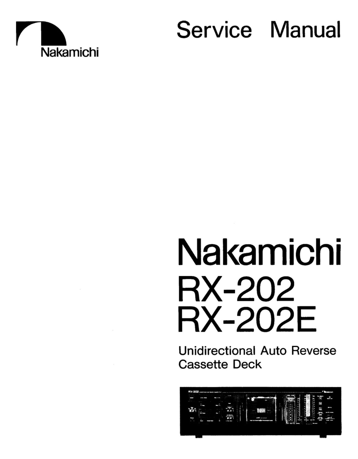
Nakamichi RX 202 Service Manual

This is the 41 pages manual for Nakamichi RX 202 Service Manual.
Read or download the pdf for free. If you want to contribute, please mail your pdfs to info@audioservicemanuals.com.

Page: 1 / 41
left right
Nakamichi RX 202 Service Manual

Extracted text from Nakamichi RX 202 Service Manual (Ocr-read)


Page 2

CONTENTS

NH

9

10.
11.

1.

General ...................................................................... 1
Mechanical Adjustments ...................................................... 2
2 1. Tape Guide Height Check for Record/Playback Head and Erase Head ..................... 2
2 2. Head Base Stroke Check .................................................. 2
2 3. Record/Playback Azimuth Alignment and Height Check ............................. 2
2 4. Pressure Adjustment of Pressure Roller ......................................... 2
2 5. Slide Base Position Adjustment (on the Logic P.C.B. Assy) ........................... 2
2 6. Tape Travelling Check .................................................... 3
2 7. Reel Motor Speed Adjustment in Play Mode ..................................... 3
2 8. Tape Speed Adjustment .................................. . . . .............. 3
2. 9. Lubrication ........................................................... 3
Parts Location for Electrical Adjustment ................................................ 4
Electrical Adjustments and Measurements ............................................... 6
4. 1. Adjustment and Measurement Instructions ...................................... 5
4. 2. Playback Frequency Response Adjustment ...................................... 7
4. 3. Dolby NR Circuit Check .................................................. 8
Mechanism Assy and Parts List ....... . ......... . .................................... 9
5. 1. Synthesis ............................................................ 9
5. 2. Chassis Ass y (A01) ...................................................... 10
5. 3. Rear Panel Assy RX202 (801) .............................................. 11
5. 4. Synthesis Mechanism Ass y (302) ............................................. 11
5. 5. S Mechanism Ass y (001) .................................................. 12
5. 6. RS Mechanism Assy (CO2) ................................................. 12
5. 7. Mechanism Assy (D01) ................................................... 13
5. 8. Motor Holder Assy (E01) ................................................. 14
5. 9. S Slide Chassis Ass y (E02) ................................................. 14
5. 10. Main Chassis Ass y (E03) .................................................. 14
Mounting Diagrams and Parts List ....................................... . ............ 15
6. 1. Power Switch P. C. B. Ass y ................................................. 15
6. 2. Shut-off P.C.B. Assy ............................... . ..................... 15
6. 3. Lid Lamp P.C.B. Assy .................................................... 15
6. 4. Eject Switch P.C.B. Assy .................................................. 15
6. 5. Tape Switch P.C.B. Assy .................................................. 16
6. 6. Volume P.C.B. Ass'y ..................................................... 16
6. 7. Counter P.C.B. Assy ..................................................... 17
6. 8. Control Switch P.C.B. Assy ................................ . . ..... . ........ 17
6. 9. Fader P.C.B. Assy ...................................................... 18
6. 10. MaianCB Assy ....................................................... 20
6.11. Logic P. C. B. Ass'y ...................................................... 24
Schematic Diagrams ........................................... . ............. . . . . 26
7. 1. Attention to Servicemen .................................................. 26
7. 2. 10 Block Diagrams ............................ . ......................... 26
7. 3. Schematic Diagrams ..................................................... 27
Wiring Diagram ................................................................ 30
Block Diagrams .............................. . . . . ............................. 31
Timing Chart and Eq. Amp. Frequency Response .......................................... 32
Specifications ..... . .......... . .............. ........ ........ 34
GENERAL

1.1. Voltage Selector
Voltage selector is installed on the rear panel for other version o! the N akamichi RX-202.
This voltage selector can select either 120 V or 220-240 V at customers disposal.

1.2. Packing Materials and Owners Manual

Part No. Domain: Qty
0F03725A Carton Box 3x202 1
0F08748A Carton Box RX202E 1
0F087 26A Packing 2
00042943 Owners Manual (3x202 (U.s.A.. Canada I: Australia) I: RX202E (UK)) 1
0D04296B Owners Manual (RX202 (Japan)) 1
0D04295A Owners Manual (3x202 (Others) ls RX202E (220V Class 2) 1

Page 7

STEP

ITEM

SIGNAL
SOURCE

4

OUTPUT
CONNECTION

MODE

ADJUST-
HINT

REMARKS

10

Record
Level
Calibration
and
Recording
Bias Current
Adlustment

400 Hz (0 dB).
400 H

z
10 kHz

(-20 dB) and
17 kHz

(-20 dB)

to input Jacks

VTVM to
TP101. TP201
and

'lP102. TP202
on Main P.C.B.
and

VTVM and
Distortion Meter
to Output Jacks

Record and Playback
'lape SW - ZXISX/Ex

Ed. SW - 70 us

(ZXISX)
120 its (EX)

Dolby N3 SW -

C-TypeIB-Tyml
OFF

MPX 8W - OFF

Main P.C.B.

is?
vniozynzoz

SX:
V3103.V3203
2x-

Vilma/R204

Tape SW P.C.B.
(Bin)

ZX:
V3105,V3205
8X:
V3108.V3208

ex:
V3107.V3207

Adjustment should be made in the order 0! zx.
SK and EX.

1.
2.
3.
4.

5.

599'

10.

11.
12.

14.
15.

16.

17.

Set the Dolby N3 switch to C-Type.
Connect a VTVM to 'lPlOl ('lP201) on the
Main P.C.B. Assy.

Set the 3X-202 in Record/Purse mode.
Feed in 400 Hz. then adjust the Input Level
control to obtain 350 mV (0 dB) on the
VTVM.

Load a reference ZX tape (DA09087B).
reference SX tape (DA090258) and refer-
ence EXII tape (DA090668).

. Adlust Record Cal. V3102 (V3202) for

ZX. V3103 (V3203) for SK and V3104
(V3204) for mm to center positions.

. Connect the VTVM to TP102 (TP202) on

the Main P.C.B. Assy. Adiust Bias V3105
(V3205) tor ZX. V3106 (V3206) tor sx
and V3107 (V3207) for E)! to obtain the
following bias current in Record/Pause
mode (the VTVM is connected across a 10-
ohm resistor).

zx: approx. 1 mA

SX: approx. 0.5 mA

EXII: approx. 0.3 mA
Connect the VTVM to the Output Jacks.
Feed in 400 Hz (-20 dB) and 17 kHz (~20
:22}: then record. rewind and play them

Adjust Bias V3105 (V3206) for zx.

V3106 (V3206) for sx and V3107

(V3207) for EXII to obtain the same play-

back levels at 400 Hz (-20 dB) and 17 kHz

(-20 dB) on the VTVM.

Feed in 400 Hz (0 dB). then record. rewind

and play it back.

Adjust Record Cal. V3102 (V3202) {or

21!. V3108 (V3208) (or SX and V3104

(V3204) tor EXII to obtain 0 dB on the

VTVM.

Repeat above 9 and 10 two or three times

to obtain optimum pertormance.

Set the Dolby N3 switch to OFF.

Feed in 400 Hz (-20 dB). 10 kHz (-20 dB)

and 17 kHz (-20 dB). then record. rewind

and play them back.

Check to insure that the playback levelsare

within -20 dB :8 dB against the levels in

Dolby N3 C-lype.

Set the Dolby N3 switch to B-Type.

Feed in 10 kHz (-20 dB) and 17 kHz (-20

33$ then record. rewind and play them
a .

Check to insure that the levels are within

-20 dB 12 dB esainst the levels in 130le

N3 OFF.

Check to insure whether the total harmonic

distortion is less than 1.0% for ZX and EXII

tapes and 1.2% for S): tape.

It above is not sufficient. repeat 9 to 16 till

satisfactory results are obtained.

11

Overall
Frequency
Response
Adlustrnent

400 Hz (0 dB)
and 20 Hz to
17 kHz

(-20 dB) to
input Jacks

VTVM to
Output Jacks

Record and Playback
'lape SW - ZX/SX [EX

31. SW - 70 us

(ZXISX)
120 its (EX)
Dolby NR. SW -- OFF

MPX SW - OFF

Main P.C.B.
L102.L202

Set the 3x-202 in Record/Purse mode.
Feed in 400 Hz. then set the Input Level
control to obtain 0 dB (500 mV) on the
VTVM.

Decrease the generator output control by 20
dB.

Feed in 20 Hz to 17 kHz (-20 dB) and
record. rewind and play them back. then
check to insure whether the output levels
are within -20 dB 14 dB.

11' above is not sufficient. adjust L102
(L202) to obtain approx. --20 dB on the
V'lVM, then conduct step 10 Record Level
Calibration and Recording Bias Current
Adjustment.

11 above is not sufficient. precise re-sdjust-
ment of step 8 Playback Frequency 3e-
sponse. replacement of Record/Playback
Head or check on item 2.6 Tape Travelling
Check will be required.

12

Crosstalk
Measure-
ment

1 kHz to
Input Jacks

1 kHz Band Pass
Filter end VTVM
to Output Jacks

Record and Playback

Tape SW -- 2X
Eu. SW .. 70 in

Dolby NR SW - 0F?

MPX SW -- OFF

. Erase the tape with bulk eraser.

Adjust the input Level control to obtain
0 dB on the V'lVM. and record the signals
on the reference ZX tape (DA09087B).

8. Turn the cassette tape the other way round

and play it back.
Measure the difference between 2 and 3.

Page 8

SIGNAL OUTPUT ADJUST
3", Inn sconce CONNECTION none. MEN? murmurs
1. Erase the tape with bull: eraser.
Channel 1 km and Pm figfgwi" 3" 2. Adiust the Input Level control to obtain
13 Separation 1 kHz to Fm" md V'rVM Eq 8, _ 70 as 0 tip on the V'rVM. and set the Balance
M""° "'9 d to Output Jacks noihy NR sw - on °°° ° ° mm "fl (1)-
ment MPX sw _ OFF 8. Record. rewind and play it back. then mea-
sure the R ch (L ch) level.
1. Erase the tape with bulk eraser.
100 H B d 2. Adjust the Input Level control to obtain
m m 100 Hz to p... pfini'ina 3333:3133)? tafidtgfifiédogn ;
1 mm Input Jacks VTVM to 8" " m" a. Rewind the tape. set the Input Level centre]
0? Jacks to minimum. and then record azain.
4. Rewind the tape. play it back. and then
measure the difference between 2 and 3.
1. Set the Dolby N R switch to B-TYDOIC-Tm.
2. Feed ii; 400 Hz. then record. rewind and
bafi play it ack.
8m to IBM Cum. $3353: 3: 3. Adjust the Input Level control to obtain 39:.
15 Noise Ratio 00 Hz to 31:59:43? Eq. SW _ 70 u, total harmonic distortion in Playbaclt mode.
. 0'1 b NR _ 4. Set the Input Level control to nunimum
Measure Input Jacks Meter .0 Do] 3! SW then record |
Inent Output Jada Mpx 3;?333' 5. After rewound. 'play back and check the
output level difference between 3 and 4.
Note: The filter of lHF-A curve mall be used in
the measurements.
Record and Playback 1. Adjust the Input Level control to obtain
Total Tape sw - ZXISXIEX 0 dB 0" 3 VTVM-
._ 70 2. Record. rewind and play it back.
Harmonie 400 Hz .0 VTVM and Eq. SW us .
16 Distortion Woman Me: (ZXISX) 3. Read the distortion meter and Check to
Measure. 1119M click! to Output Jacks 120 I (EX) insure that the distortion as as follows:
ment Dolby NR sw -OFF 311 - - - - - g: g; :2:
WSW-0" zx::::::1:mn...
Wow] 3 Hi: Speed Wow [Flutter
Flutter and Wow] Plum
17 Measure- Flutter Tape 361:3; :3. eke Eq. 8W - 70 us Play back and read the wow/nutter meter.
ment (DAOQOOGC)
4.2. Playback Frequency Response Adiusttnent m 3 £8, .33,

Flu. 4.1 and 4.2 show the playback amp. circuit for adjustment

and the playback equalization curve.
This adjustment will be required It playback level is not mlfleient
during playing back a 20 RB: 18 heouency response tape.

The peaking portion of the equalization curve compensates the
up less of the playback head. Peaking level isvaried by the short
eireuit of 3110 (8210) or R195 (R295).

no

GAIN Bl

I00

MO

00 (K 2'!
FREQUENCY (Hr)

FR. 4.2

spores. zes
won 2

0 1K

VRIOI
(W20!)

Ouleet

seep
H

Clo. (C290 000?

H

C007 lCZOI

120's

Fi. 4.1

Q sum
(D seen
09 one

20K