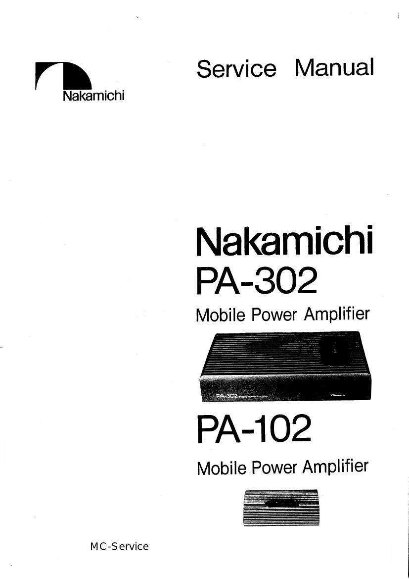
Nakamichi PA302 pwr sch

This is the 17 pages manual for Nakamichi PA302 pwr sch.
Read or download the pdf for free. If you want to contribute, please mail your pdfs to info@audioservicemanuals.com.

Page: 1 / 17
left right
Nakamichi PA302 pwr sch

Extracted text from Nakamichi PA302 pwr sch (Ocr-read)


Page 2

1, General
2. Removal Procedure '
2. 1. Fuse '

3. Adjustment -------
3. 1. Parts Location for Adjustment:
3. 2. Adjustment Procedures ~

4. Mechanism Assy and Parts List-
4. 1. Synthesis ................
4. 2. TR Block B Assy (A01)-
4. 3. TR Block C Assy (A02) -
4. 4. TR Block A Ass (A03)-

5. Mounting Diagramsm-

émmmphwwarbwé

5. 1. Main P.C.Bi Assy ~ -7
5. 2. Power Supply P.C B. Ass '7
5. 3. Fuse P.C.B. Assy -7
6. Schematic Diagram 8
6. 1. Main PCB. Assy- ~8
6. 2. Power Supply PC B Ass'y (with Fuse RC 13. Assy) -9
7. Wiring Diagram - 0
8. Block Diagram" 10
9 Specifications .. ....................... 10

CONTENTS "

1. GENERAL

1.1. Notes on Order of Spare Parts
Note that the Main P.C.B. Assy and Power Supply PCB. Assy do not include the following parts. Please order the excluded parts
together with P.C.B. Assy to complete a set of PCB. Ass'y.

Excluded Parts

P. c. B. Assy

Part Name Remarks
Main PCB. Assy 0 TR Block A Assy ------------------- 1pce. Ref. No. 15 in Fig. 4.1.
(BA07735A) (BAO7738A) Consists of transistors and
heat sink.

Power Supply PCB. Assy 0 TR Block B Assy "'lpce. Ref. No. 10 in Fig. 4.1.

(BA07736A) (BA07657A) Consists of transistors and
heat sink.
0 TR Block C Assy ------------------- 1pce. Ref. No. 12 in Fig. 4.1.
(BA07658A) Consists of diodes and
heat sink.
0 Converter Transformer ------------ 1pce. Ref. No. 23 in Fig. 4.1.
(0B50164A) (T401)
0 Choke Coil . Ref. No. 24 in Fig. 4.1.
(0351314B) . (L401)
1.2. Destination
0 USA. and Canada
0 Other
0 Europe
0 Japan
1

MC-Service