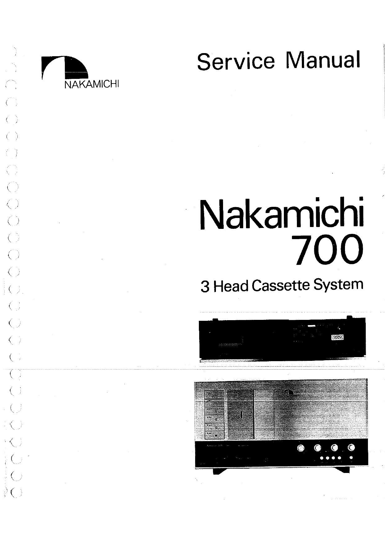
Nakamichi 700 Service Manual

This is the 96 pages manual for Nakamichi 700 Service Manual.
Read or download the pdf for free. If you want to contribute, please mail your pdfs to info@audioservicemanuals.com.

Page: 1 / 96
left right
Nakamichi 700 Service Manual

Extracted text from Nakamichi 700 Service Manual (Ocr-read)


Page 1

A, /\ y/\

//\

\

/-\

AA

NAKAMICHI

Service Manual

' Nakamichi "
700

3 Head Cassette System

Page 2

1. General
2. Principle of Operation

2.1.

Mechanisms

2.1 .1. 3 Head Configuration
2.1.2. Double Capstan Tape Drive
2.1.3. Reel Drive Mechanism

2.2.

Amp. Circuits

2.2.1. Flecord Dolby Circuit
2.2.2. P.B. Dolby Circuit
2.2.3. P.B. Head Amp.

2.2.4. MIC Amp. Board
2.2.5. Mixing Amp. 81 Limiter
2.2.6. Rec. E0. Amp.

2.2.7.

as Osc. 8t 400H2 Osc.

2.2.8. Line Amp. & Meter Amp.
2.2.9. Power Supply

2.3.

Mechanism Control Circults

2.3.1. Logic Control
2.3.2. Shutoff Sensor 84 Detector
2.3.3. Azimuth Alignment Detector
2.3.4. Motor Governor

3. Dismantling

3.1. Front Panel Ass'y

3.2 Head Mount Base Ass'y (Previous Type) and Pressure Roller Arm Ass'y
3.3. Head Mount Base (E) Ass'y (New Type) and Pressure Roller Arm Ass'y
3.4. Head Base Damper Ass'y and Eject Damper Bracket Ass'y

3.5. Real Drive Mechanism Assy

3.6. Flywheel Ass'y

3.7. Control Button Assy

3.8. Sub-Motor Ass'y

3.9. Main Motor Assy

3.10. Transformer
3.11. Main Board Ass'y
3.12.. Power Supply Ass'y
3.13. P.B. Head Amp. Assy, P.B. Dolby NR Assy and Rec. Dolby NR Ass'y
3.14. Front Control Assy and Switch Board Ass'y
3.15. 400Hz Osc. Sw. P.C.B. Ass'y
3.16. Shwofi Luminous P.C.B. Ass'y and Shutoif Sensor P.C.B. Ass'y
4. Chock-out Procedures

4.1
4.2

. Check Methods

Check-out Procedures for Inspection

5. Measurement and Maintenance Instrumens

5.1
5.2

. Maintenance Instruments

Measurement Instruments and Connection

6. Mechanical Measurements and Adjustments

6.1

6.2

6.3
6.4

6.5
6.6

6.7

. Take-up, Fast Fonrvard and Rewind Torque Adjustment
6.1.1. Ta'ke-up Torque Adjustment

6.1.2. Fast Forward and Rewind Torque Adjustment
. Headblock

6.2.1. ' Head Replacement Procedures

6.2.2. Head Height Adjustment (Previous Type)
6.2.3. Head Height Adjustment (New Type)

6.2.4. Playback Head Adjustment

6.2.5. Record Head Adjustment

6.2.6. Erase Head Adjustment

. Flywheel Adjustment

. Tape Travelling Adjustment

6.4.1. Checkout Method

6.4.2. Adjustment

. Adjustment of Real Drive Mechanism Ass'y

. Damper Adjustment

6.6.1. Head Base Damper

6.6.2. Eject Damper

. Lubrication

mammoth

10

12
15
16
18
20
22
23
24
25
25
32
34
37
41

42

335633

$86$8£§$$538$$388

an
note

( l
(f r
l :7
l 3
i/ fl
< l
< i

Wen
\

/\ /A\

(#2
i

(.Q

(1*

i
\../

/\
\fl,

(.
k;

Page 16

Input
FET h Out
Amp] Time UC

Blas
Const. AmpZ Trap __0

VRlOl

EQ.

Fig. 2.13 Playback Amp. System Diagram

2.2.4. MIC AMP.

Fig. 2.14 shows a microphone amplifier circuit. This circuit board carries a DIN amplifier (DIN
AMP.), a microphone amplifier (MIC AMP.) and a blending microphone amplifier (BLEND MIC
AMP.). The DIN connector and pin connector are communicated to the LINE VOLUME directry.
When pin connector is used, disconnect the DIN cord for avoiding the influence of the DIN cord
stray capacitor.

Microphone amplifier (MIC AMP): Since the signal level of this imput is usually low, Q702 is
provided to broaden the dynamic range. This circuit is a modified shunt regulated push-pull system
which is devised for varying the load of Q701 with the position of the MIC VOLUME control. For
a large microphone output, this circuit is used at a reduced MIC VOLUME. In this case, however,
the voltage gain of Q701 decreases because the load resistance of Q701 is reduced. Since voltage
gain of the conventional microphone amplifier is constant, its amplification characteristics are not
good for large input signals and its dynamic margin is about 40 dB. However, the microphone
amplifier described here can be used without distortion for input voltages up to 0.5V because of its
broad dynamic margin which is greater than 60 dB. Thus, no microphone attenuator is necessary. If
neither a DIN microphone nor amm'icrophone plug are connected, the output of this circuit is
grounded.

As the blending microphone circuit (BLEND MIC) is the same as the microphone amplifier, its
explanation is omitted.

The voltage values indicated as 0.5 mV, 10 mV, etc., at the input terminals of the circuit board
show that when each VOLUME control on the panel concerned is set at its maximum position, the
LEVEL METER indicates 0 dB for each of these values. The output of this circuit is combined with
the input of the mixing amplifier. The output impedance of this circuit is designed to be very high,
above 270 ha, while the input impedance of the mixing amplifier of the next stage is designed to be

low, therefore, with little interference between the VOLUME controls, ideal mixing is possible.

-15-

r\

Page 50

Mechanical adjustments have to be performed prior to this
adjustment. Refer to the 8. Parts Location for Electrical
Adjustment, Fig. 8-1, Fig. 8-2" for the positions of semi-fixed
volume and test point.

7.1. Tape Speed
Signal Source
3kHz Speed Wow Flutter Tape (DAOQOOSA)
Measurement Connection
Frequency Counter to Output Jacks
Mode
CONTROL BUTTON - Playback
MONITOR SW - Tape
TAPE SELECTOR SW - CrOz
Adjustment
(1) Set the Pitch Control Knob to "0" position.
(2) Adjust the Speed Control VRSOZ to obtain 3kHz on
Frequency Counter.
VR502 - Motor Governor P.C.B.

TAPE SPEED
ADJUST _\(DLUME

Fig. 7.1

72. Meter Level Calibration
Signal Source
IkHz 0.3V to Input Jacks or 1kHz 0.1V to DIN lnput.
Measurement Connection
VTVM to Test Point TPl (Main P.C.B.) -GND (Lch).
TP2 (Main P.C.B.) -GND (Rch).
Mode
MONITOR SW-SOURCE
Adjustment
(1) Adjust the line input level controls to obtain 100mV12mV
on VTVM.
(2) Adjust the Meter Calibration VR155, 255 to obtain 0 118 on
Level Meters.
VR155 iLch), VR255 (Rch) - Main P.C,B.


3
with.
9
ll
I177 '
' mmrm cm 47,."
and
19C II M.)
.L. a. no


um:
um. am.

III I Dll

u n

Fig. 7.2

_50_

7.3. AOOHz Test Tone
Mode
MONITOR SW - SOURCE
400Hz TEST TONE SW . 0N
Adjustment
Adjust the Tone Calibration VR351 so that the level meter of
the L channel indicate 0 dB.
VR351 -Main P.C.B.
Note: If the level meters of the L and R channels are not
balanced, modification of R175 or R275 will be required.

7.1L 19KHz MPX Filter
Signal Source

19kHz 0.3V to Input Jacks or 0.1V to DIN Input.
Measurement Connection

VTVM and Frequency Counter to Output Jacks or DIN

Output.
MODE
MONITOR SW - SOURCE
MPX SW - OFF
DOLBY NR SW - OUT
Adjustment

(ll Adjust the line input level controls to obtain 0 dB (W) on
the Level Meters and VTVM.

(2) Set the MPX SW to ON.

(3) Adjust MPX Filter Coils L154, 254 to obtain the minimum
reading on VTVM.
L154 (Lch), L254 (R chl - Main P.C.B.
Note: Frequency has to be leHztlOOHz on Frequency

Counter.

m3 llnl) up; n'
a...

m7: 2.7K A
c i ii: 5

cm ":cm 1200! 2

Tw 9

L?

D

5

r-

,_

Fig. 7.4 <

ISK

lOK
FREQUENCY (Hz)

Fig. 7.5

/'\.

{,
\