Nakamichi 680ZX Service Manual

This is the 72 pages manual for Nakamichi 680ZX Service Manual.
Read or download the pdf for free. If you want to contribute, please mail your pdfs to info@audioservicemanuals.com.

Page: 1 / 72
left right
Nakamichi 680ZX Service Manual

Extracted text from Nakamichi 680ZX Service Manual (Ocr-read)


Page 1

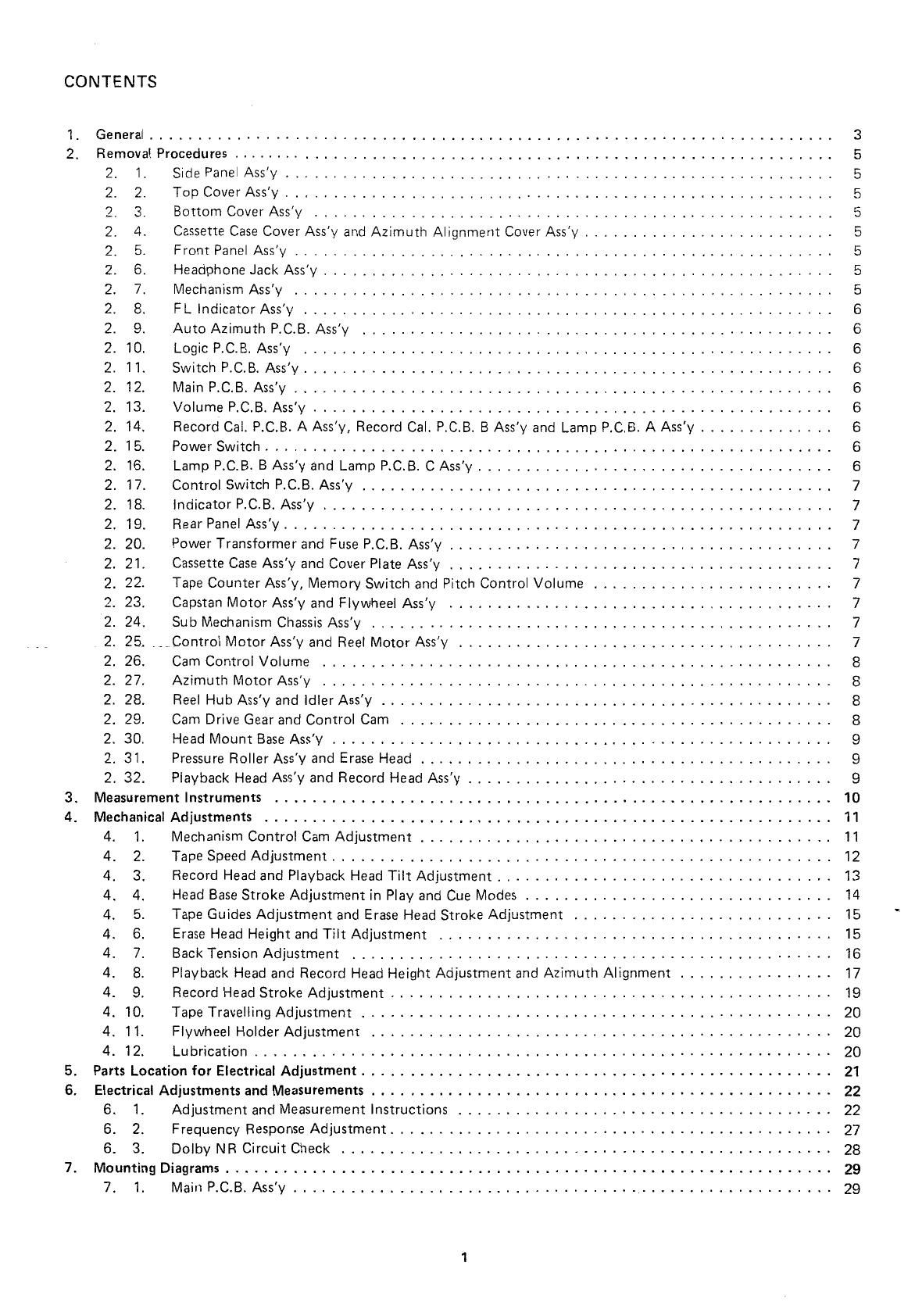
CONTENTS

1. General ....................................................................... 3
2. Removal Procedures ............................................................... 5
2. 1. Side Panel Assy ................................................. 5
2. 2. Top Cover Assy ....................................................... 5
2. 3. Bottom Cover Assy .................................................... 5
2. 4, Cassette Case Cover Ass'y and Azimuth Alignment Cover Ass'y ......................... 5
2. 5. Front Panel Assy ........................................................ 5
2, 6. Headphone Jack Assy ..................................................... 5
2. 7. Mechanism Assy ........................................................ 5
2. 8. FL Indicator Assy ....................................................... 6
2. 9. Auto Azimuth P.C.B. Assy ................................................. 6
2. 10. Logic P.C.B. Ass'y ....................................................... 6
2, 11. Switch P.C.B. Ass'y ....................................................... 6
2. 12. Main P.C.B. Ass'y ........................................................ 6
2. 13. Volume P.C.B. Ass'y ...................................................... 6
2. 14. Record Cal. P.C.B. A Ass'y, Record Cal. P.C.B. B Ass'y and Lamp P.C.B. A Assy .............. 6
2. 15. Power Switch ........................................................... 6
2. 1B. Lamp P.C.B. B Ass'y and Lamp P.C.B. C Ass'y ..................................... 6
2. 17. Control Switch P.C.B. Ass'y ................................................. 7
2. 18. Indicator P. C. B. Ass'y ..................................................... 7
2. 19. Rear Panel Ass y .............. 7
2. 20. Power Transformer and Fuse P. C. B Ass y ........................................ 7
2. 21. Cassette Case Ass' y and Cover Plate Ass y ........................................ 7
2. 22. Tape Counter Assy, Memory Switch and Fitch Control Volume ......................... 7
2. 23. Capstan Motor Assy and Flywheel Ass'y ........................................ 7
2. 24. Sub Mechanism Chassis Ass'y ................................................ 7
2. 25. ...,Control Motor Ass'y and Reel Motor Assy ....................................... 7
2. 26. Cam Control Volume ..................................................... 8
2. 27. Azimuth Motor Assy ..................................................... 8
2. 28. Reel Hub Ass'y and Idler Assy ............................................... 8
2. 29. Cam Drive Gear and Control Cam ............................................. 8
2. 30. Head Mount Base Assy .................................................... 9
2. 31. Pressure Roller Assy and Erase Head ........................................... 9
2. 32. Playback Head Ass'y and Record Head Ass'y ...................................... 9
3. Measurement Instruments .......................................................... 10
4. Mechanical Adjustments ........................................................... 11
4. 1. Mechanism Control Cam Adjustment ........................................... 11
4. 2. Tape Speed Adjustment .................................................... 12
4. 3. Record Head and Playback Head Tilt Adjustment ................................... 13
4. 4. Head Base Stroke Adjustment in Play and Cue Modes ................................ 14
4. 5. Tape Guides Adjustment and Erase Head Stroke Adjustment ........................... 15
4. 6. Erase Head Height and Tilt Adjustment ......................................... 15
4. 7. Back Tension Adjustment .................................................. 16
4. 8. Playback Head and Record Head Height Adjustment and Azimuth Alignment ................ 17
4. 9. Record Head Stroke Adjustment .............................................. 19
4. 10. Tape Travelling Adjustment ................................................. 20
4. 11. Flywheel Holder Adjustment ................................................ 20
4. 12. Lubrication ............................................................ 20
5. Parts Location for Electrical Adjustment ................................................. 21
6. Electrical Adjustments and Measurements ................................................ 22
6. 1. Adjustment and Measurement Instructions ....................................... 22
6. 2. Frequency Response Adjustment .............................................. 27
6. 3. Dolby NR Circuit Check ................................................... 28
7. Mounting Diagrams ............................................................... 29
7. 1. Main P.C.B. Ass'y ........................................................ 29

Page 2

8.

7. 2 Switch P.C.B. Ass'y ....................................................... 31
7. 3 Record Cal. P.C.B. A Assy .................................................. 31
7. 4. Record Cal. P.C.B. B Ass'y .................................................. 31
7. 5. Logic P.C.B. Assy ....................................................... 33
7. 6 Fuse P.C.B. Assy ........................................................ 35
7. 7 Pin Jack P.C.B. Ass'y ...................................................... 36
7. 8 Auto Shut-off P.C.B. Assy .................................................. 36
7. 9. Volume P.C.B. Ass'y ...................................................... 36
7. 10. Auto Azimuth P.C.B. Assy ................................................ 36
7. 11. Control Switch P.C.B. Ass'y ................................................ 37
7. 12. Lamp P.C.B. A Ass'y ..................................................... 37
7. i3. Lamp P.C.B. B Assy ...................................................... 37
7. 14. Lamp P.C.B. C Assy ...................................................... 37
7. 15. Indicator P.C.B. A Assy ........ . .......................................... 37
7. 16. indicator P.C.B. B Assy .................................................... 37
7. 17. Indicator P.C.B. C Assy .................................................... 38
Mechanism Ass'y and Parts List ....................................................... 39
8. 1. Synthesis ............................................................. 39
8. 2 Front Panel Assy (A01) ................................................... 42
8. 3 Mechanism Ass'y GBOZX (A02) ............................................... 43
8. 4. Chassis Assy (A03) ....................................................... 46
8. 5. Front Panel Escutcheon Assv (B01) ........................................... 46
8. 6 Control Button Assy (802) ................................................. 46
8. 7 Flywheel Holder Ass'y (C01) ................................................ 46
8. 8. Sub Mechanism Chassis Assy (002) ............................................ 47
8. 9. Main Mechanism Chassis Ass'y (C03) ........................................... 50
8. 10. FL indicator Ass'y (001) ................................................... 55
8. )1. Calibration Case Ass'y (002) ................................................ 55
8. 12. Volume Holder Assy (D03) ........................... ' ...................... 55
8. 13. Headphone Jack Assy (1304) ................................................ 55
S. 14. Reflector Assy (D05) ..................................................... 55
8. 15. Counter Lamp Assy (D06) .................................................. 55
8. 16. Power Switch Holder Ass'y (007) ............................................. 55
8. 17. Rear Panel Ass'y (D08) .................................................... 58
8. 18. Reel Motor Ass'y (E01) .................................................... 58
8. 19. Control Motor Ass'y [E02) .................................................. 58
8. 20. Azimuth Alignment Motor Assy (E03) .......................................... 58
8. 21. Head Mount Base Ass'y (F01) ................................................ 58
8. 22. Supply Pressure Roller Assy (F02) ............................................ 58
8. 23. Take-up Pressure Roller Assy (F03) ............................................ 59
8. 24. Head Base Assy D (F04) ................................................... 59
8. 25. Cassette Case Holder L Assy (F05) ............................................ 59
8. 26. Cassette Case Holder R Ass'y (F06) ............................................ 59
8. 27. Auto Shut-off Ass'y (F07) .................................................. 59
8. 28. Pneumatic Damper Assy (F08) ............................................... 59
8. 29. Pitch Control Holder Assy (F09) ............................................. 59
8. 30. Azimuth Motor Ass'y (C501) ................................................. 59
8. 31. P- 8L Playback Head Assy (H01) .............................................. 59
8 32. R- 8L Record Head Ass y (H02) ............................................... 59
Overall Timing Chart .............................................................. 61
Eq. Amp. Frequency Response ....................................................... 62
10. 1. Standard Speed (1-7/8 ips) .................................................. 62
10.1.1. Playback Frequency Response ............................................. 52
10.1.2. Record Current Frequency Response ......................................... 62
10. 2. Half-Speed (15/16 ips) ..................................................... 62

Page 8

2.26. Cam Control Volume

Refer to Fig. 2.9.

(1) Remove Sub Mechanism Chassis Ass'y referring to
item 2.24.

(2) Remove F08, then disassemble F09 (Volume Cou-
pier).

(3) Remove F10, then disassemble F11 (Cam Control
Volume].

2.27. Azimuth Motor Assy

Refer to Fig. 2.9.

(1) Remove Sub Mechanism Chassis Assy referring to
item 2.24.

(2) Remove F12, then disassemble F13 (Azimuth Align-
ment Motor Ass'y).

(3) Remove F14, then disassemble F15 (Azimuth Motor
Ass'v) and F16 (Drive Pulley Assy).

2.28. Reel Hub Ass'y and Idler Ass'y

Refer to Fig. 2.9.

(1) Remove Sub Mechanism Chassis Ass'y referring to
item 2.24.

(2) Remove F17 (Real Hub Head), then disassemble F18
(Reel Hub 8 Ass'y), F19 (Reel Hub Take-up Assy).
F20 (Reel Hub Supply Assy), F21 (Back Tension
Assy) and F22 (Back Tension Spring).

(3) Remove F23, then disassemble F24 (Idler Assy).

2.29. Cam Drive Gear and Control Cam

Refer to Fig. 2.9.

(1) Remove Sub Mechanism Chassis Assy referring to
item 2.24.

(2) Remove F25, then disassemble F26 (Cam Drive Gear).

(3) Remove F27, then disassemble F28 (Counter-Load
Arm Ass'y).

(4) Remove F29, then disassemble F30 (Control Cam).

F13

Page 11

4. MECHANICAL ADJUSTMENTS

4.1. Mechanism Control Cam Adjustment

Before adjustment, disassemble the Front Panel Assy.
then remove the Cover Plate referring to items 2.5 and
2.21.

(1) Offset Adjustment of Control Motor Driver

(a) Refer to Figs. 4.1 and 4.2.

Adjust VR402 and VR4D3 on the Logic P.C.B. to
locate approximately at the middle of the variable
range. Then turn ON the Power Switch.

VR402 (for Cam position stop)

VR403 (for Cam position play)

(b) Press the Stop Switch to set the N-GBOZX in stop
mode.

Adjust VR402 (for stop) so that the "5" mark on the
Cam corresponds to the pointer on the mechanism
chassis.

(c) Press the Play Switch to set the N-GSOZX in playback

mode.
(Cam will rotate, and the position marked with "PY"
comes to the pointer.) Adjust VR403 (for play) so
that the "PY" mark on the Cam corresponds to the
pointer.

it!) Repeat above (b) and (c) 2 - 3 times so that the "S"
and PY" marks on the Cam correspond to the
pointer accurately in stop and playback modes re-
spectively.

(This adjustment is required because the position
adjusted by one volume will be slightly changed when
the other volume is adjusted.)

(e) Set the N-GBOZX in FF. pause, or cue mode by press-
ing each switch (press FF and Pause Switches to set
the N-BBOZX in cue mode) and check to insure that
the pointer is in a range of "F", "PS", or "CU"
mark respectively.

(f) If out of the range, precise adjustment for each posi-
tion according to (2) Offset Fine Adjustment of
Control Motor Driver" will be required.


Mechanism
Chassrs

(2) Offset Fine Adjustment of Control Motor Driver
Adjust only if a satisfactory result is not obtained in
(1) Offset Adjustment of Control Motor Driver". This
adjustment is made by changing the value of the fixed
resistors on the Logic P.C.B.

Note: The value of voltage is typical value.

(a) Observation Point of Reference Voltage

Observe the each voltage at the sliding contact of the
Carn Control Volume VFMOS (10 k9) in stop, fast (FF or
REW), pause, record and playback modes.

(b) Reference Voltage
Reference voltage at the sliding contact of VR405 (Cam
Control Volume) in each mode is as follows:

Mode Reference Volta e (Ty ical Value)
Sto 3.0 V
p )-L7v:d25v
Fast (FF/REW) 1.3 V
Pause -2.8 V
zevav
Play -5.4 V}
(c) Resistors for Adjustment
Mode Ref. No. Typical Value
Stop R461 9.1 k9 (F)
Fast (FF/REW) R462 4.32 kg (F)
Pause R445 287 k!) (F)
Play R443 174 k9 (F)

(d) Adjustment Procedures
1) Press the Stop Switch to set the N-GBOZX in stop
mode.

Adjust the value of R461 to obtain 3.0 V ($0.6 V)

at the sliding contact of V3405.

Note: When R461 is adjusted, the reference voltage
in fast (FF or REW) mode is changed. There
fore, re-check of the reference voltage in fast
(FF or REW) mode is required. If the refer-
ence voltage is out of the range, re-adjustment
of R462 according to next step 2) is neces-

sary.
~IZV + l2V
2
In
(I

8

Eh
0
CN-9

Fig. 4.2

Page 17

(4)

(5)
(6)

Set the Cassette Deck in stop mode, and remove the
Tension Arm Adjustment Cassette (DAOQOSEA),
then set the Cassette Deck in cue mode.

In cue mode, check to insure that the gap is found
between the Supply Reel Hub B Assy and the Felt
of Back Tension Ass'y as shown in Fig. 4.15.

Load the Back Tension Gauge (DA09055Al.

Set the Cassette Deck in play mode and read the
torque value of Back Tension Gauge.

If the value is in a range of 6 g-cm to 10 g-cm, adjust-
ment is not necessary. If not, change the installation
point of the Back Tension Spring as shown in Fig. 4.
16, and obtain the torque of 7 gcm to 9 gram range.

4.8. Playback Head and Record Head Height Adjustment

(1)

and Azimuth Alignment
Playback Head Height Adjustment and Azimuth
Alignment

Refer to Fig. 4.17.

(a)
(bi
ic)
id)
(2)

(fl

(2)

Set the Monitor Switch to the Tape position, then
connect a VTVM to the Output Jacks.

Load a 1 kHz Track Alignment Tape (DA09007A),
then set the N-GBOZX in play mode.

Turn the PH Height Gear until the outputs of both
channels become minimum.

Load a 15 kHz Azimuth Tape (DA09004A), then set
the N-GBOZX in play mode.

Turn the PH Azimuth Alignment Screw until the out-
puts of both channels become maximum.

Repeat above steps (b) through (e) one or two times
to obtain optimum performance.

Record Head Height Adjustment and Azimuth Align-
ment

Refer to Figs. 4.17 - 4.20.

(a)

Set the N-6802X in stop mode.

Turn the Azimuth Motor in the Azimuth Alignment
Motor Assy by hand so that the Alignment Indicator
corresponds to the pointer of the Azimuth Alignment
Motor Assy as shown in Fig. 4.18.

Remove the Azimuth Alignment Wire by pulling out
from the Azimuth Alignment Motor Assy. ln this
case, do not move the Slide Lever of the Azimuth
Alignment Wire. Short both leads of capacitor C903
on the Auto Azimuth P.C.B. Ass'y with a jumper
wrre.

17

(b)

(c)

(dl

(e)

(f)

(a)

Increase

Increase

Fig. 4.16

Set the Monitor Switch to the Tape position, then

connect a VTVM to the Output Jacks.

Load a Reference SX Tape (DA09025A). Set the Eq.

Switch to the 70 us position and the Tape Switch to

the SX position. Then set the N-GSOZX in record and

play mode.

Set the Display Switch to the Cal. position, then turn

the RH Height Gear until the outputs of both chan-

nels become maximum.

Feed in 15 kHz (-20 dB), then set the N-BSOZX in

record and play mode. Turn the RH Azimuth Align-

ment Screw until the outputs of both channels be-

come maximum.

Repeat above steps (d) and (e) one or two times to

obtain optimum performance.

After completion of the above adjustments, perform

the following electrical adjustments first at standard

tape speed, then at half tape speed.

Note: Use the same side of the same tape used in

the above steps.

(1) Standard Speed (1-7/8 ipsl:

a) Set the Monitor Switch to the Tape position and

the Display Switch to the Cal. position, then set

the N-GBOZX in record and play mode.

Adjust VR404 on the Logic P.C.B. Assy so that

the cursors are coincident with the rightmost

edges of the main displays on the FL Level Indi-

cators.

c) Adjust VR901 on the Auto Azimuth P.C. B.
Ass'y so that the Azimuth Motor stops its rota-
tion. '

bi

Page 55

8-10. FL Indicator ASS'Y (D01) - 8.11. Calibration Case Ass'y (002) 8.14. Reflector Assy (DOS)

01 03 02
LO1-m 09 L%F
-LO1
Fig. 8.14

8.15. Counter Lamp Ass'y (D06)

L02

Fig. 8.10 Fig. 8.16

55