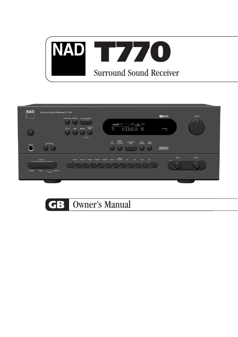
Nad T 770 Owners Manual

This is the 22 pages manual for Nad T 770 Owners Manual.
Read or download the pdf for free. If you want to contribute, please mail your pdfs to info@audioservicemanuals.com.

Page: 1 / 22
left right
Nad T 770 Owners Manual

Extracted text from Nad T 770 Owners Manual (Ocr-read)


Page 1

Warning: To reduce the risk of fire or electric shock, do not expose this unit to rain or moisture. The lightning flash with an arrowhead symbol within an equilateral triangle, is intended to alert the user to the presence of uninsulated dangerous voltage within the products enclosure that may be of sufficient magnitude to constitute a risk of electric shock to persons. The exclamation point within an equilateral triangle is intended to alert the user to the presence of important operating and maintenance (servicing) instructions in the literature accompanying the product. Do not place this unit on an unstable cart, stand or tripod, bracket or table. The unit may fall, causing serious injury to a child or adult and serious damage to the unit. Use only with a cart, stand, tripod, bracket or table recommended by the manufacturer or sold with the unit. Any mounting of the device on a wall or ceiling should follow the manufacturers instructions and should use a mounting accessory recommended by the manufacturer. An appliance and cart combination should be moved with care. Quick stops, excessive force and uneven surfaces may cause the appliance and cart combination to overturn. Read and follow all the safety and operating instructions before connecting or using this unit. Retain this notice and the owners manual for future reference. All warnings on the unit and in its operating instructions should be adhered to. Do not use this unit near water; for example, near a bath tub, washbowl, kitchen sink, laundry tub, in a wet basement or near a swimming pool. The unit should be installed so that its location or position does not interfere with its proper ventilation. For example, it should not be situated on a bed, sofa, rug or similar surface that may block the ventilation openings; or placed in a built-in installation, such as a bookcase or cabinet, that may impede the flow of air through its ventilation openings. The unit should be situated from heat sources such as radiators, heat registers, stoves or other devices (including amplifiers) that produce heat. The unit should be connected to a power supply outlet only of the voltage and frequency marked on its rear panel. The power supply cord should be routed so that it is not likely to be walked on or pinched, especially near the plug, convenience receptacles, or where the cord exits from the unit. Unplug the unit from the wall outlet before cleaning. Never use benzine, thinner or other solvents for cleaning. Use only a soft damp cloth. The power supply cord of the unit should be unplugged from the wall outlet when it is to be unused for a long period of time. Care should be taken so that objects do not fall, and liquids are not spilled into the enclosure through any openings. This unit should be serviced by qualified service personnel when: A. The power cord or the plug has been damaged; or B. Objects have fallen, or liquid has been spilled into the unit; or C. The unit has been exposed to rain or liquids of any kind; or D. The unit does not appear to operate normally or exhibits a marked change in performance; or E. The device has been dropped or the enclosure damaged. DO NOT ATTEMPT SERVICING OF THIS UNIT YOURSELF. REFER SERVICING TO QUALIFIED SERVICE PERSONNEL Upon completion of any servicing or repairs, request the service shops assurance that only Factory Authorized Replacement Parts with the same characteristics as the original parts have been used, and that the routine safety checks have been performed to guarantee that the equipment is in safe operating condition. REPLACEMENT WITH UNAUTHORIZED PARTS MAY RESULT IN FIRE, ELECTRIC SHOCK OR OTHER HAZARDS. ATTENTION POUR ÉVITER LES CHOC ELECTRIQUES, INTRODUIRE LA LAME LA PLUS LARGE DE LA FICHE DANS LA BORNE CORRESPONDANTE DE LA PRISE ET POUSSER JUSQUAU FOND. CAUTION TO PREVENT ELECTRIC SHOCK, MATCH WIDE BLADE OF PLUG TO WIDE SLOT FULLY INSERT. If an indoor antenna is used (either built into the set or installed separately), never allow any part of the antenna to touch the metal parts of other electrical appliances such as a lamp, TV set etc. CAUTION POWER LINES Any outdoor antenna must be located away from all power lines. OUTDOOR ANTENNA GROUNDING If an outside antenna is connected to your tuner or tuner-preamplifier, be sure the antenna system is grounded so as to provide some protection against voltage surges and built-up static charges. Article 810 of the National Electrical Code, ANSI/NFPA No. 70-1984, provides information with respect to proper grounding of the mast and supporting structure, grounding of the lead-in wire to an antenna discharge unit, size of grounding conductors, location of antenna discharge unit, connection to grounding electrodes and requirements for the grounding electrode. a. Use No. 10 AWG (5.3mm2) copper, No. 8 AWG (8.4mm2) aluminium, No. 17 AWG (1.0mm2) copper-clad steel or bronze wire, or larger, as a ground wire. b. Secure antenna lead-in and ground wires to house with stand-off insulators spaced from 4-6 feet (1.22 - 1.83 m) apart. c. Mount antenna discharge unit as close as possible to where lead-in enters house. d. Use jumper wire not smaller than No.6 AWG (13.3mm2) copper, or the equivalent, when a separate antenna-grounding electrode is used. see NEC Section 810-21 (j). EXAMPLE OF ANTENNA GROUNDING AS PER NATIONAL ELECTRICAL CODE INSTRUCTIONS CONTAINED IN ARTICLE 810 - RADIO AND TELEVISION EQUIPMENT. NOTE TO CATV SYSTEM INSTALLER: This reminder is provided to call the CATV system installers attention to Article 820-40 of the National Electrical Code that provides guidelines for proper grounding and, in particular, specifies that the ground cable ground shall be connected to the grounding system of the building, as close to the point of cable entry as practical. FOR U.S.A. MODEL FCC INFORMATION FOR USER CAUTION: Changes or modifications not expressly approved by the manufacturer for compliance could void the users authority to operate. NOTE: This equipment has been tested and found to comply with the limits for a Class B digital device, pursuant to part 15 of the FCC Rules. These limits are designed to provide reasonable protection against harmful interference in a residential installation. This equipment generates, uses, and can radiate radio frequency energy and, if not installed and used in accordance with the instructions, may cause harmful interference to radio communications. However, there is no guarantee that interference will not occur in a particular installation. If this equipment does cause harmfiul interference to radio or television reception, which can be determined by turning the equipment off and on, the user is encouraged to try to correct the interference by one or more of the following measures: -Reorient or relocate the receiving antenna. -Increase the separation between the equipment and receiver. -Connect the equipment into an outlet on a circuit different from that to which the receiver is connected. -Consult the dealer or an experienced radio/TV technician for help. CAUTION RISK OF ELECTRIC SHOCK DO NOT OPEN ATTENTION:RISQUE DE CHOC ELECTRIQUE NE PAS OUVRIR CAUTION:TO REDUCE THE RISK OF ELECTRIC SHOCK, DO NOT REMOVE COVER (OR BACK). NO USER SERVICEABLE PARTS INSIDE. REFER SERVICING TO QUALIFIED SERVICE PERSONNEL. IMPORTANT SAFETY INSTRUCTIONS 2

Page 2

3 FRONT PANEL CONTROLS REAR PANEL CONNECTIONS

Page 12

By briefly tapping the or you can engage manual tuning respectively up or down the frequency band for precise tuning to a specific frequency. With each successive tap of the keys, the tuner will take 0.05 MHz steps on FM so you can accurately tune into the desired frequency. For AM the tuning steps can be 9 kHz or 10 kHz, depending on the version of your T770. This tuning mode can also be useful when trying to receive a radio station which is too weak for the auto search mode. When tuned accurately to a station, TUNED will light up in the display. With stations carrying RDS information, the stations RDS name is displayed, Program Service (PS; normally the stations calling letters, BBC R3, for instance). Refer to the separate chapter Storing, recalling and naming Presets for more information. NOTE:The 120V versions (North America) do not have RDS (Radio Data System). 16. FM MUTE/MODE This button combines two functions; it switches the tuner from Stereo to Mono and disengages the muting circuitry at the same time. The muting circuit will mute the tuner in between radio stations when searching or tuning. This way the tuning noise is avoided. Very weak radio station signals however may be suppressed by the muting circuit. If such a very weak station is in stereo it will have a high level of background hiss. Switching to Mono Mode and disengaging the muting circuit by depressing the FM MUTE/MODE button will allow the station to be heard and will cancel most or all of this background noise. In normal operation the mute circuit is engaged, the display indicates FM MUTE. Press the FM Mute/Mode button to disengage the muting circuit and switch from stereo to mono reception. FM MUTE will extinguish in the display. Also, STEREO will extinguish if a stereo broadcast was received. Press the FM Mute/Mode switch again to return to Auto Stereo FM operation. SURROUND FUNCTIONS 17. EXT. 5.1CH Selects the multi-channel output signal from the DVD player or external decoder source (such as DTS, MPEG, etc.) connected to the EXT. 5.1 CH input as the active input. NOTES:The Speakers B (No. 3), Digital Audio Selector (No. 18) and Surround mode (No. 19) buttons do not have any effect in this mode. No audio signal is available from the Tape 1, Tape 2, Video 1 and Video 2 outputs when the EXT. 5.1 CH input has been selected. 18. DIGITAL AUDIO SELECTOR With the Digital Audio selector button you can assign which one of the Input Selectors will be linked to either the Digital Audio 1, Digital Audio 2 or Digital Audio 3 inputs. When a Digital Audio input is linked to one of the Input selectors, whenever a digital source is sensed at the Digital Audio input, the Digital Audio input will be used instead of the corresponding analogue audio input. To assign a Digital Audio input to a specific Input Selector button: -Press the desired input button (except AM, FM, Tape 2 Monitor and EXT. 5.1 CH.) -Press the Digital Audio Selector button. The "DIGITAL AUDIO" box will light up in the display with the first available digital input. -Press the Digital Audio Selector button again to until the desired digital input lights up (either 1,2 or 3). Digital Input 1 is the optical input; Digital Audio input 2 and Digital Audio input 3 are the coaxial inputs.The next time this input is selected, the chosen Digital Audio input will automatically be selected as well. NOTES:It is not possible to select a digital input if Digital Audio input 1, Digital Audio input 2 and Digital Audio input 3 have already been assigned. You must first de-select the desired Digital Audio input from the Input Selector button it has been assigned to. TO DE-SELECT A DIGITAL AUDIO INPUT -Select the input to which the Digital Audio Input is assigned (the display indicates which Digital Audio Input is assigned to the selected input). -Press the Digital Audio Selector until the Digital Audio extinguishes in the display. The Digital Audio input has now been de-selected from the chosen input. When no digital source is available (not connected or source is switched off) the associated Digital Audio input number will blink. Once a digital signal is available and the input has locked on to the digital signal it will remain lit. 19. SURROUND MODE With the Surround Mode and buttons the available surround sound modes can be selected. The selected Surround mode is permanently indicated in the display area and is also shown for 3 seconds in the large alphanumeric section of the display. The Surround Mode buttons scroll through the available surround sound modes: Surround Mode Off Dolby Pro Logic EARS Surround mode Off, etc. With Dolby Digital surround sources Dolby Pro Logic and EARS are not available: Surround Mode Off Dolby Digital. If Dolby Pro Logic or EARS is selected the T770 will automatically switch to Dolby Digital. Dolby Digital has six independent channels available in total: Left, Center, Right, Surround left, Surround Right and an Effects Channel (Subwoofer). Dolby Digital is only available as a Surround Mode if the source is Dolby Digital and a Digital Audio input is used. The Dolby Digital signal conforms to Dolbys AC-3 standard, which allows for several channel configurations. The channel configuration is shown the display together with the input selected. For example, with regular Dolby Digital sources the display will show ch3/2, indicating that there are 3 front channels and 2 surround channels available. Dolby Pro Logic decodes the center and surround sound signals embedded in stereo movie sound tracks from e.g. video, Laser Disc or TV. To decode correctly, the source must be a Dolby Surround or Dolby Stereo soundtrack. GB 13