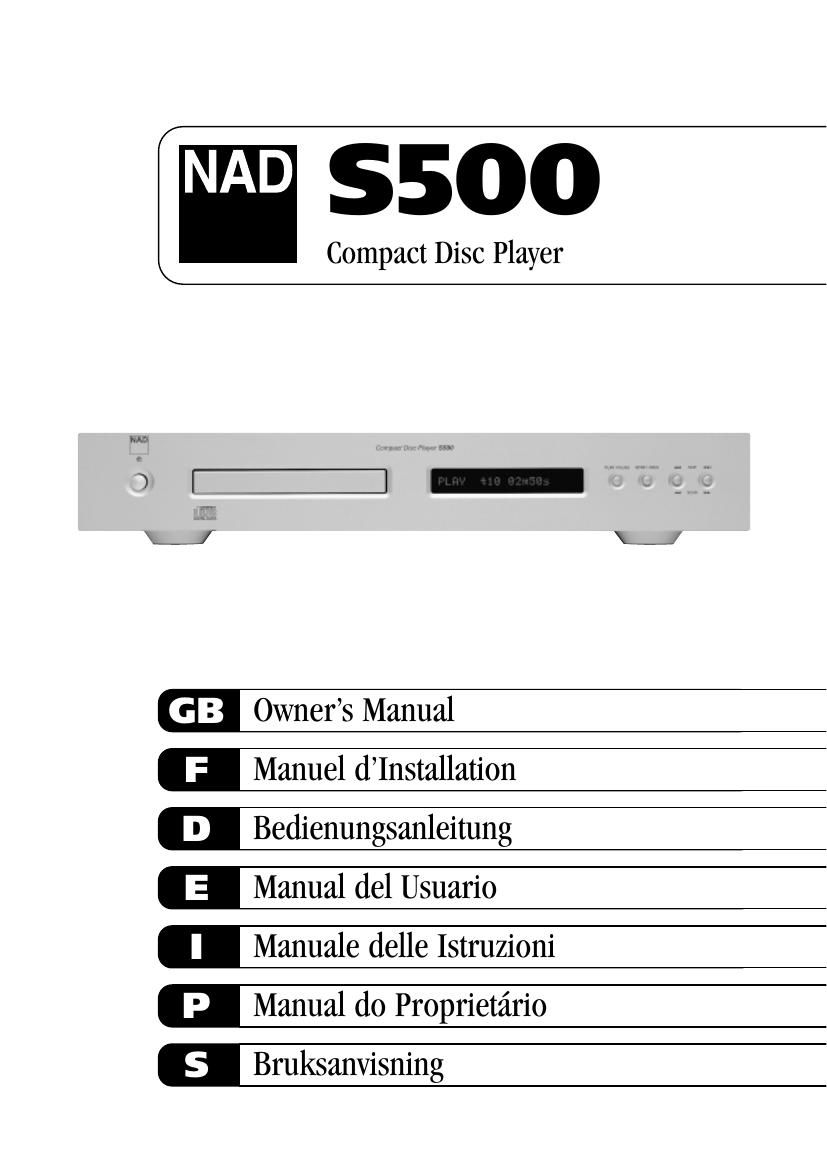
Nad S 500 Owners Manual

This is the 32 pages manual for Nad S 500 Owners Manual.
Read or download the pdf for free. If you want to contribute, please mail your pdfs to info@audioservicemanuals.com.

Page: 1 / 32
left right
Nad S 500 Owners Manual

Extracted text from Nad S 500 Owners Manual (Ocr-read)


Page 1

Warning: To reduce the risk of fire or electric shock, do not expose this unit to rain or moisture. The lightning flash with an arrowhead symbol within an equilateral triangle, is intended to alert the user to the presence of uninsulated dangerous voltage within the products enclosure that may be of sufficient magnitude to constitute a risk of electric shock to persons. The exclamation point within an equilateral triangle is intended to alert the user to the presence of important operating and maintenance (servicing) instructions in the literature accompanying the product. Do not place this unit on an unstable cart, stand or tripod, bracket or table. The unit may fall, causing serious injury to a child or adult and serious damage to the unit. Use only with a cart, stand, tripod, bracket or table recommended by the manufacturer or sold with the unit. Any mounting of the device on a wall or ceiling should follow the manufacturers instructions and should use a mounting accessory recommended by the manufacturer. An appliance and cart combination should be moved with care. Quick stops, excessive force and uneven surfaces may cause the appliance and cart combination to overturn. Read and follow all the safety and operating instructions before connecting or using this unit. Retain this notice and the owners manual for future reference. All warnings on the unit and in its operating instructions should be adhered to. Do not use this unit near water; for example, near a bath tub, washbowl, kitchen sink, laundry tub, in a wet basement or near a swimming pool. The unit should be installed so that its location or position does not interfere with its proper ventilation. For example, it should not be situated on a bed, sofa, rug or similar surface that may block the ventilation openings; or placed in a built-in installation, such as a bookcase or cabinet, that may impede the flow of air through its ventilation openings. The unit should be situated from heat sources such as radiators, heat registers, stoves or other devices (including amplifiers) that produce heat. The unit should be connected to a power supply outlet only of the voltage and frequency marked on its rear panel. The power supply cord should be routed so that it is not likely to be walked on or pinched, especially near the plug, convenience receptacles, or where the cord exits from the unit. Unplug the unit from the wall outlet before cleaning. Never use benzine, thinner or other solvents for cleaning. Use only a soft damp cloth. The power supply cord of the unit should be unplugged from the wall outlet when it is to be unused for a long period of time. Care should be taken so that objects do not fall, and liquids are not spilled into the enclosure through any openings. This unit should be serviced by qualified service personnel when: A. The power cord or the plug has been damaged; or B. Objects have fallen, or liquid has been spilled into the unit; or C. The unit has been exposed to rain or liquids of any kind; or D. The unit does not appear to operate normally or exhibits a marked change in performance; or E. The device has been dropped or the enclosure damaged. DO NOT ATTEMPT SERVICING OF THIS UNIT YOURSELF. REFER SERVICING TO QUALIFIED SERVICE PERSONNEL Upon completion of any servicing or repairs, request the service shops assurance that only Factory Authorized Replacement Parts with the same characteristics as the original parts have been used, and that the routine safety checks have been performed to guarantee that the equipment is in safe operating condition. REPLACEMENT WITH UNAUTHORIZED PARTS MAY RESULT IN FIRE, ELECTRIC SHOCK OR OTHER HAZARDS. ATTENTION POUR ÉVITER LES CHOC ELECTRIQUES, INTRODUIRE LA LAME LA PLUS LARGE DE LA FICHE DANS LA BORNE CORRESPONDANTE DE LA PRISE ET POUSSER JUSQUAU FOND. CAUTION TO PREVENT ELECTRIC SHOCK, MATCH WIDE BLADE OF PLUG TO WIDE SLOT FULLY INSERT. If an indoor antenna is used (either built into the set or installed separately), never allow any part of the antenna to touch the metal parts of other electrical appliances such as a lamp, TV set etc. CAUTION POWER LINES Any outdoor antenna must be located away from all power lines. OUTDOOR ANTENNA GROUNDING If an outside antenna is connected to your tuner or tuner- preamplifier, be sure the antenna system is grounded so as to provide some protection against voltage surges and built-up static charges. Article 810 of the National Electrical Code, ANSI/NFPA No. 70-1984, provides information with respect to proper grounding of the mast and supporting structure, grounding of the lead-in wire to an antenna discharge unit, size of grounding conductors, location of antenna discharge unit, connection to grounding electrodes and requirements for the grounding electrode. a. Use No. 10 AWG (5.3mm2) copper, No. 8 AWG (8.4mm2) aluminium, No. 17 AWG (1.0mm2) copper-clad steel or bronze wire, or larger, as a ground wire. b. Secure antenna lead-in and ground wires to house with stand-off insulators spaced from 4-6 feet (1.22 - 1.83 m) apart. c. Mount antenna discharge unit as close as possible to where lead- in enters house. d. Use jumper wire not smaller than No.6 AWG (13.3mm2) copper, or the equivalent, when a separate antenna-grounding electrode is used. see NEC Section 810-21 (j). EXAMPLE OF ANTENNA GROUNDING AS PER NATIONAL ELECTRICAL CODE INSTRUCTIONS CONTAINED IN ARTICLE 810 - RADIO AND TELEVISION EQUIPMENT. NOTE TO CATV SYSTEM INSTALLER:This reminder is provided to call the CATV system installers attention to Article 820-40 of the National Electrical Code that provides guidelines for proper grounding and, in particular, specifies that the ground cable ground shall be connected to the grounding system of the building, as close to the point of cable entry as practical. CAUTION RISK OF ELECTRIC SHOCK DO NOT OPEN ATTENTION:RISQUE DE CHOC ELECTRIQUE NE PAS OUVRIR CAUTION:TO REDUCE THE RISK OF ELECTRIC SHOCK, DO NOT REMOVE COVER (OR BACK). NO USER SERVICEABLE PARTS INSIDE. REFER SERVICING TO QUALIFIED SERVICE PERSONNEL. IMPORTANT SAFETY INSTRUCTIONS 2

Page 2

3 FRONT PANEL CONTROLS REAR PANEL CONNECTIONS REMOTE CONTROL CLASS 1 LASER product LUOKAN 1 LASERPLAITE KLASS 1 LASERAPPARAT THIS DIGITAL APPARATUS DOES NOT EXCEED THE CLASS B LIMITS FOR RADIO NOISE EMISSIONS FROM DIGITAL APPARATUS AS SET OUT IN THE RADIO INTERFERENCE REGULATIONS OF THE CANADIAN DEPARTMENT OF COMMUNICATIONS. LE PRESENT APPAREIL NUMVERIQUE N'EMET PAS DE BRUITS RADIOELECTRIQUES DEPASSANT LES LIMITES APPLICABLES AUX APPAREILS NUMERIQUES DE LA CLASSE B PRESCRITES DANS LE REGLEMENT SUR LE BROUILLAGE RADIO ELECTRIQUE EDICTE PAR LE MINISTERE DES COMMUNICATIONS DU CANADA. WARNING! INVISIBLE LASER RADIATION WHEN OPEN AND INTERLOCKS DEFEATED. AVOID EXPOSURE TO BEAM. VORSICHT! UNSICHTBARE LASERSTRAHLEN TRITT AUS, WENN DECKEL GEÖffnet und wenn sicherheitsverriegelung ÜberbrÜckt ist. Nicht dem strahl aussetzen. ADVARSEL - USYNLIG LASERSTRÅLING VED ÅBNING, NÅR SIKKERHEDSAFBRYDERE ER UDE AF FUNKTION.UNDGÅ UDSÆTTELSE FOR STRÅLUNG. ADVARSEL - USYNLIG LASERSTRÅLING NÅR DEKSEL ÅPNES OG SIKKERHEDSLÅS BRYTES. UNNGÅ EKSPONERING FOR STRÅLEN. VARNING - OSYNLIG LASERSTRÅLNING NÄR DENNA DEL ÄR ÖPPNAD OCH SPÄRRAR ÄR URKOPPLADE. STRÅLEN ÄR FARLIG. VARO! - AVATTAESSA JA SUOJALUKITUS OHITETTAESSA OLET ALTTIINA NÄKYMÄTÖNNTÄ LASERSÄTEILYLLE. ÄLÄ KATSO SÄTEESEEN.

Page 11

HINWEISE ZUR AUFSTELLUNG Die Aufstellung des Compact Disc Players sollte auf einer ebenen und vibrationsfreien Oberfläche erfolgen. Starke Erschütterungen oder der Betrieb in gekippter Stellung können die Spurlage des CD-Players beeinträchtigen. Solange auf ausreichend Luftzirkulation um das Gerät geachtet wird, kann der CD-Player im Stapel mit anderen Geräten aufgestellt werden. Wird der CD-Player in unmittelbarer Nähe eines Radiogerätes (Mittelwelle oder UKW), Video- oder Fernsehgerätes betrieben, können seine digitalen Schaltkreise Störungen beim Empfang schwacher Radiosender verursachen. Stellen Sie in solchen Fällen den CD-Player in einiger Entfernung getrennt von anderen Geräten auf oder schalten das Gerät während des Empfangs von Radio- oder Fernsehsendungen aus. COMPACT DISCS ABSPIELEN EINFACH UND UNKOMPLIZIERT 1. Verbinden Sie mit einem Stereokabel den linken (L) und rechten (R) Ausgang mit den entsprechenden Eingängen an Ihrem Verstärker. 2. Schließen Sie das abnehmbare Netzkabel an der Netzbuchse auf der Rückwand an. 3. Schließen Sie das Netzkabel an einer Netzsteckdose an. 4. Schalten Sie den CD-Player durch Drücken der Taste POWER ein. 5. Öffnen Sie die CD-Schublade durch Drücken der Taste STOP/OPEN. 6. Legen Sie eine CD mit der bedruckten Seite nach oben in die kreisrunde Vertiefung der Schublade ein. Achten Sie darauf, daß die CD in der Mitte der Vertiefung liegt. 7. Drücken Sie PLAY/PAUSE. Die Schublade schließt automatisch und das Abspielen der CD beginnt. 8. Zur Auswahl von verschiedenen CD-Titeln können Sie jederzeit SKIP oder drücken. 9. Wenn Sie die Wiedergabe kurzzeitig unterbrechen und dabei die aktuelle CD-Abspielposition beibehalten möchten, drücken Sie PLAY/PAUSE. (Drücken Sie erneut PLAY/PAUSE zum Fortsetzen der Wiedergabe). Möchten Sie das Abspielen beenden und den Tonabnehmer auf den Anfang der CD zurücksetzen, drücken Sie einmal STOP/OPEN und zweimal, wenn die Schublade geöffnet werden soll. RÜCKWANDANSCHLÜSSE 1. UNSYMMETRISCHER LINE-AUSGANG (UNBALANCED LINE OUTPUT) Verbinden Sie diese Buchsen über ein gummiisoliertes Anschlußkabel mit Ihrem Verstärker. Stecken Sie ein Ende eines Stereo-Audiokabels in die linke (obere) und rechte (untere) Ausgangsbuchsen. Verbinden Sie das andere Kabelende mit dem CD-Eingang oder einem anderen Linepegel-Eingang (Zusatzeingang AUX) Ihres Verstärkers. Schließen Sie dieses Kabel NICHT an die PHONO-Eingangsbuchsen Ihres Verstärkers an. Achten Sie darauf, daß die Stecker fest und richtig sitzen. 2. SYMMETRISCHER LINE-AUSGANG (BALANCED LINE OUTPUT) Anschlüsse für Leistungsverstärker oder Vorverstärker mit symmetrischen XLR-Steckverbindungen wie z. B. dem NAD S300. Die Standardverkabelung für diese Anschlüsse ist wie folgt: Stift 1: Gehäuseerde (GND) Stift 2: Heiß (+OUT) Stift 3: Signal-Nullpunkt (-OUT) VORTEILE SYMMETRISCHER VERBINDUNGEN Bei einer konventionellen Verbindung (unsymmetrisch) fließt der Audiosignalstrom vom CD-Player zum Verstärker durch den Kabelmittelleiter. Damit der Stromkreis geschlossen ist, fließt der Audiosignalstrom durch den Kabelaußenleiter zum CD-Player- Nullpunkt zurück. Der äußere Leiter dient dabei ebenfalls der Kabelabschirmung. Werden zwei Audiogeräte miteinander verbunden, fließen Netzrausch- und Streuverlustbrummsignale ebenfalls in der Kabelabschirmung und vermischen sich mit dem Signalrückstrom. Die daraus resultierenden Verzerrungen und Rauschsignale können von der Orientierung der Netzstecker in der Steckdose abhängen. Entwickler von HiFi-Verbindungskabeln bekämpfen diese Verunreinigungen durch einseitiges Anschließen der Abschirmung, was zur Folge hat, daß die Leistung dieser Kabel von der Verbindungsrichtung abhängig ist, d. h. davon, ob die Abschirmung am CD-Player oder am Verstärker geerdet ist. Eine symmetrische Dreileiterverbindung schließt alle diese Ungewißheiten aus. Der heiße Signalstrom und der Signalrückstrom fließen beide in Innenleitern. Die an beiden Enden am Verstärkergehäuse angeschlossene, separate Kabelabschirmung schützt das Audiosignal vor allen möglichen Interferenzen und vor Netzrauschen. 3. AES/EBU-DIGITALAUSGANG (SYMMETRISCH) Dieser professionelle Standard-Digitalausgang liefert das Signal an einem XLR/Cannon-Stecker mit der Bezeichnung AES/EBU DIGITAL OUT und erlaubt bei entsprechender Ausrüstung die höchste Qualität in der digitalen Übertragung. Der serielle Datenausgang wird nach der Fehlerkorrektur aber vor der D/A-Wandlung und Filterung abgegriffen und ist von den eingebauten D/A-Schaltkreisen durch einen Übertrager isoliert. 4. DIGITALAUSANG (DIGITAL OUTPUT) Das digitale Wiedergabesignal ist auch an diesem Ausgang verfügbar.[BH1] Er kann mit jedem digitalen Signalprozessor verbunden werden, der dem Sony/Philips-Standard (SPDIF) entspricht. Möchten Sie diesen Digitalausgang einsetzen, verbinden Sie diese Buchse mit dem CD digital oder einem äquivalenten Eingang eines Digitalprozessors. Die besten Ergebnisse werden mit einem auch für Videosignale verwendeten 75-Ohm-Koaxialkabel mit BNC- Anschlüssen an beiden Enden erzielt. D 12 NAD S500 Compact Disc Player

Page 31

WWW.NAD.CO.UK ©1998 NAD ELECTRONICS LONDON ENGLAND All rights reserved. No part of this publication may be reproduced, stored or transmitted in any form without the written permission of NAD Electronics S500 Manual 09/98 Printed in Denmark