Nad S 170 Service Information

This is the 2 pages manual for Nad S 170 Service Information.
Read or download the pdf for free. If you want to contribute, please mail your pdfs to info@audioservicemanuals.com.

Page: 1 / 2
left right
Nad S 170 Service Information

Extracted text from Nad S 170 Service Information (Ocr-read)


Page 1

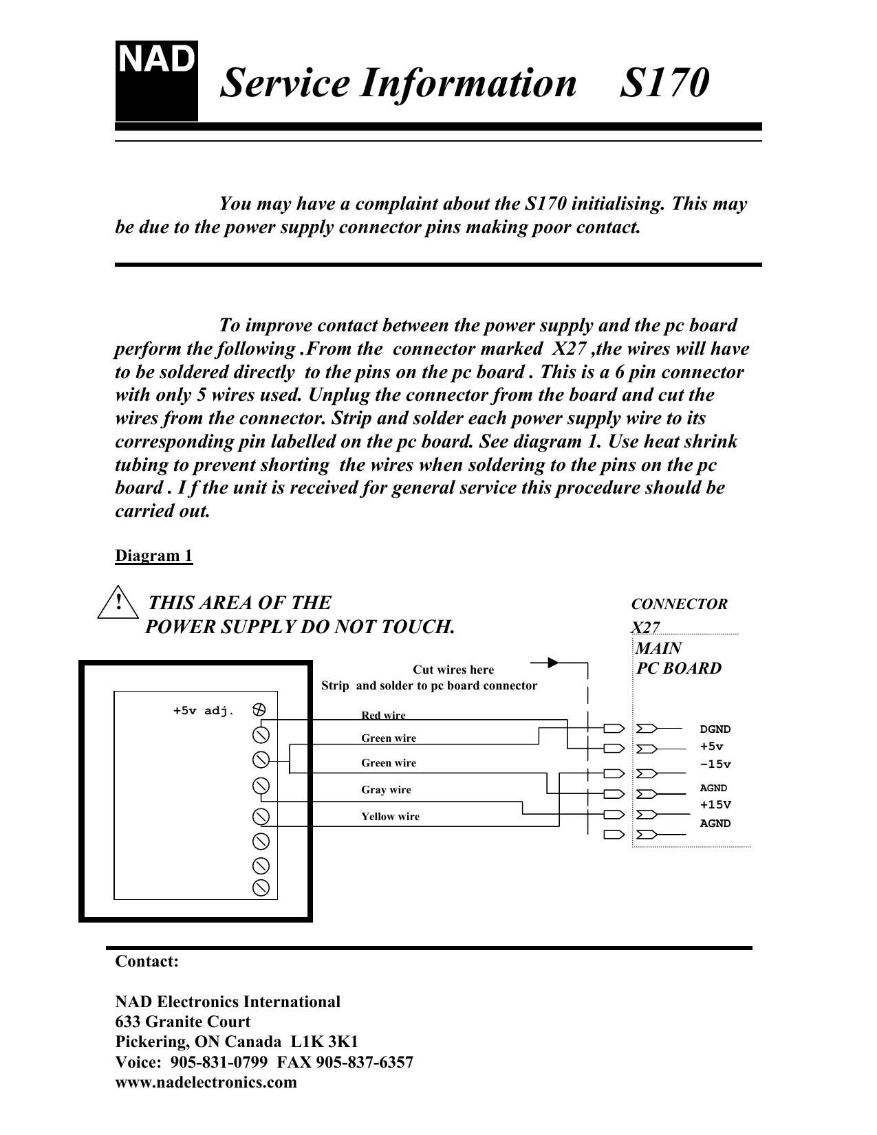
Service Information S170 You may have a complaint about the S170 initialising. This may be due to the power supply connector pins making poor contact. To improve contact between the power supply and the pc board perform the following .From the connector marked X27 ,the wires will have to be soldered directly to the pins on the pc board . This is a 6 pin connector with only 5 wires used. Unplug the connector from the board and cut the wires from the connector. Strip and solder each power supply wire to its corresponding pin labelled on the pc board. See diagram 1. Use heat shrink tubing to prevent shorting the wires when soldering to the pins on the pc board . I f the unit is received for general service this procedure should be carried out. Diagram 1! THIS AREA OF THE CONNECTOR POWER SUPPLY DO NOT TOUCH.X27 MAIN Cut wires here PC BOARD Strip and solder to pc board connector ww Contact: NAD Electronics International 633 Granite Court Pickering, ON Canada L1K 3K1 Voice: 905-831-0799 FAX 905-837-6357 www.nadelectronics.comRed wire Green wire Green wire Gray wire Yellow wireDGND +5v -15vAGND+15VAGND+5v adj.