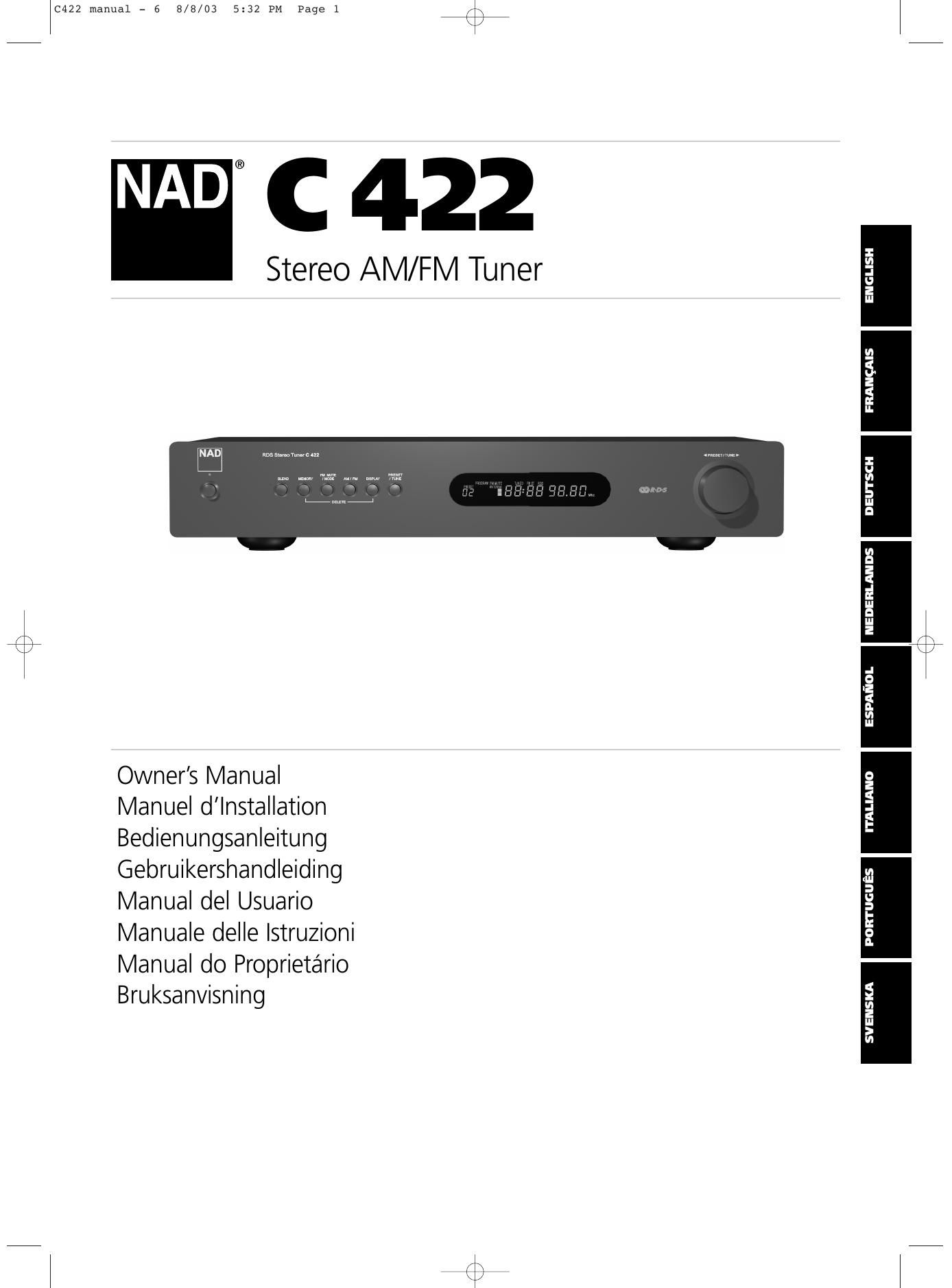
Nad C 422 Owners Manual

This is the 68 pages manual for Nad C 422 Owners Manual.
Read or download the pdf for free. If you want to contribute, please mail your pdfs to info@audioservicemanuals.com.

Page: 1 / 68
left right
Nad C 422 Owners Manual

Extracted text from Nad C 422 Owners Manual (Ocr-read)


Page 1

ENGLISH FRANÇAISDEUTSCHNEDERLANDS ESPAÑOLITALIANO PORTUGUÊS SVENSKA 2 EXPLANATION OF GRAPHICAL SYMBOLS The lightning flash with arrowhead symbol, within an equilateral triangle, is intended to alert the user to the presence of uninsulated dangerous voltage within the products enclosure that may be of sufficient magnitude to constitute a risk of electric shock to persons. The exclamation point within an equilateral triangle is intended to alert the user to the presence of important operating and maintenance (servicing) instructions in the literature accompanying the appliance. PRECAUTIONS Read the Operating Instructions carefully and completely before operating the unit. Be sure to keep the Operating Instructions for future r eference. All warnings and cautions in the Operating Instructions and on the unit should be strictly followed, as well as the safety suggestions below. INSTALLATION 1W ater and Moisture - Do not use this unit near water, such as near a bathtub, washbowl, swimming pool, or the like. 2 Heat - Do not use this unit near sources of heat, including heating vents, stoves, or other appliances that generate heat. It also should no\ t be placed in temperatures less than 5°C (41°F) or greater then 35°C (95°F). 3 Mounting surface - Place the unit on a flat, even surface. 4V entilation - The unit should be situated with adequate space around it so that proper ventilation is assured. allow 10 cm (4 in.) clearance from the rear and the top of the unit, and 5 cm (2 in.) from each side. - Do not place on a bed, rug, or similar surface that may block the ventilation openings. - Do not install the unit in a bookcase cabinet, o\ r airtight rack where ventilation may be impeded. 5 Objects and liquid entry - Take care that objects or liquids do not get inside the unit through the ventilation openings. 6 Carts and stands - When placed or mounted on a stand or cart, the unit should be moved with care. Quick stops, excessive force, and uneven surfaces may cause the unit and cart to overturn or fall. 7 Condensation - Moisture may form on the CD pickup lens when: - The unit is moved from a cold spot to a warm spot. - The heating system has just been turned on. - The unit is used in a very humid room. - The unit is cooled by an air conditioner. When this unit has condensation inside, it may not function normally. Should this occur, leave the unit for a few hours, then try to operate again. 8W all or ceiling mounting - The unit should not be mounted on a wall or ceiling, unless specified in the Operating Instructions. W ARNING! TO REDUCE THE RISK OF FIRE OR ELECTRONIC SHOCK, DO NOT EXPOSE THIS APPLIANCE TO RAIN OR MOISTURE This product is manufactured to comply with the radio interference requirements of EEC DIRECTIVE 89/68/EEC and 73/23/EEC ELECTRIC POWER 1 Power Sources - Connect this unit only to power sources specified in the Operating Instructions, and as marked on the unit. 2 Polarization - As a safety feature, some units are equipped with polarized AC power plugs which can only be inserted one way into a power outlet. If it is difficult or impossible to insert the AC power plug into an outlet, turn the plug over and try again. If it still does not easily insert into the outlet, please call a qualified service technician to se\ rvice or replace the outlet. To avoid defeating the safety feature of the polarized plug, do not force it into a power outlet. 3 AC power cord - When disconnecting the AC power cord, pull it out by the AC power plug. Do not pull the cord itself. - Never handle the AC power plug with wet hands, as this could result in fire or shock. - Power cords should be routed to avoid being severely bent, pinched, or walked upon. Pay particular attention to the cord from the unit to the power socket. -A void overloading AC outlets and extension cords beyond their capacity, as this could result in fire or shock. 4 Extension cord - To help prevent electric shock, do not use a polarized AC power plug with an extension cord, receptacle, or other outlet unless the polarized plug can be completely inserted to prevent exposure of the blades of the plug. 5W hen not in use - Unplug the AC power cord from the AC outlet if the unit will not be used for several months or more. When the cord is plugged in, a small amount of current continues to flow to the unit, even when the power is turned off. CAUTION Modifications or adjustments to this product, which are not expressly approved by the manufacturer, may void the users right or authority to operate this product. MAINTENANCE Clean the unit only as recommended in the Operating Instructions. DAMAGE REQUIRING SERVICE Have the unit serviced by a qualified service technician if - The AC power plug has been damaged. - Foreign objects or liquid have gotten inside the unit. - The unit has been exposed to rain or water - The unit does not seem to operate normally. - The unit exhibits a marked change in performance. - The unit has been dropped, or the cabinet has been damaged DO NOT ATTEMPT TO SERVICE THE UNIT YOURSELF C422 manual - 6 8/8/03 5:32 PM Page 2

Page 2

ENGLISH FRANÇAIS DEUTSCH NEDERLANDS ESPAÑOL ITALIANO PORTUGUÊS SVENSKA 3 ANTENNA INFORMATION If an indoor antenna is used (either built into the set or installed separately), never allow any part of the antenna to touch the metal par\ ts of other electrical appliances such as a lamp, TV set etc. CAUTION POWER LINES Any outdoor antenna must be located away from all power lines. OUTDOOR ANTENNA GROUNDING If an outside antenna is connected to your tuner or tunerpreamplifier, be sure the antenna system is grounded so as to provide some protection against voltage surges and built-up static charges. Article 810 of the National Electrical Code, ANSI/NFPA No. 70-1984, provides information with respect to proper grounding of the mast and supporting structure, grounding of the lead-in wire to an antenna discharge unit, size of grounding conductors, location of antenna discharge unit, connection to grounding electrodes and requirements for the grounding electrode. a. Use No. 10 AWG (5.3mm2) copper, No. 8 AWG (8.4mm2) aluminium, No. 17 AWG (1.0mm2) copper-clad steel or bronze wire, or larger, as a ground wire. b. Secure antenna lead-in and ground wires to house with stand-off insulators spaced from 4-6 feet (1.22 - 1.83 m) apart. c. Mount antenna discharge unit as close as possible to where leadin enters house. d. Use jumper wire not smaller than No.6 AWG (13.3mm2) copper, or the equivalent, when a separate antenna-grounding electrode is used. see NEC Section 810-21 (j). EXAMPLE OF ANTENNA GROUNDING AS PER NATIONAL ELECTRICAL CODE INSTRUCTIONS CONTAINED IN ARTICLE 810 - RADIO AND TELEVISION EQUIPMENT. NOTE TO CATV SYSTEM INSTALLER: This reminder is provided to call the CATV system installers attention to Article 820-40 of the National Electrica l Code that provides guidelines for proper grounding and, in particular, specifies that the ground cable ground shall be connected to the grounding system of the building, as close to the point of cable entry as practical. OWNERS RECORD For your convenience, record the model number and serial number (you will find them on the rear of your set) in the space provided below. Please r efer to them when you contact your dealer in case of difficulty. Model No. : Serial No. : C422 manual - 6 8/8/03 5:32 PM Page 3

Page 4

5 ENGLISH FRANÇAIS DEUTSCH NEDERLANDS ESPAÑOL ITALIANO PORTUGUÊS SVENSKA NOTES ON INSTALLATION Y our NAD C 422 should be placed on a firm, level surface. Avoid placing the unit in direct sunlight, near sources of heat and damp or in poorly ventilated positions. It comes with RCA leads for connection to your amplifier. Ensure that leads and connectors are not damaged in any way and all connectors are firmly pushed home. If the unit is not going to be used for some time, disconnect the plug from the AC socket. Should water get into your NAD C 422, shut off the power to the unit and remove the plug from the AC socket. Have the unit inspected by a qualified service technician before attempting to use it again. DO NOT REMOVE THE COVER; THERE ARE NO USER- SERVICEABLE PARTS INSIDE. Use a dry soft cloth to clean the unit. If necessary, lightly dampen the cloth with soapy water. Do not use solutions containing benzyl or other volatile agents. QUICK START Use the RCA-to-RCA lead to connect the NAD C 422 left & right outputs to the Tuner Input of your amplifier. 1 Plug in the AC power cord. 2 Connect C 422s output to amplifier. 3 Connect AM and FM antenna. 4 Press the POWER button (No. 1) to turn on the NAD C 422. 5 Press the AM/FM button (No. 6) to select AM or FM reception. 6 Press Preset/Tune button so that "PRESET" isnt lit in display; the tuner is now in Tune mode. 7 Use TUNE/PRESET or to select a station. REAR PANEL CONNECTIONS 1 FM Antenna - A ribbon wire FM antenna is included and should be connected to the FM connector at the rear of the unit using the supplied "balun" adapter (see fig 1). The ribbon aerial should be mounted on a vertical surface and placed so that it forms a "T". Experiment with placement of the antenna to find the position that gives the best signal strength and lowest background noise. An inadequate FM signal normally results in high levels of hiss, especially in stereo, and interference from external electrical sources. In areas of poor FM reception, the tuner sections performance can be improved by using an externally mounted FM antenna. A qualified aerial installer will be able to advise and fit a recommended aerial for your r eception conditions. 2 AM Antenna - An AM loop antenna is supplied with the NAD C 422 and is required for AM reception. To connect the AM antenna, first press the keys on the Antenna terminals downwards. Insert the bare antenna wires into the two terminal holes and push the connector keys upwards again to secure the connection (see fig 2). T est various positions for the antenna but always ensure the loop is placed vertically for best reception. Placing the antenna close to large metal items such as metal shelves or radiators may interfere with r eception. 3 Output - Using twin RCA-to-RCA leads, connect to the left (white) and right (red) audio outputs to the "Tuner" input or other line-level input such as "Aux" input of your amplifier. Do not connect this cable to the amplifiers "Phono" input. 4 IR in - The IR IN connector is used to pass commands from other units fitted with IR OUT connectors. This allows centralized control of a complete system, and also allows some of the basic functions of other NAD components (such as a CD player or cassette-deck) also equipped with IR IN to be controlled with an NAD system remote control. To function with such other units, connect the C 422s IR IN to the IR OUT on the other unit. IR IN connectors can be daisy- chained, IN to OUT, so that a whole system can be controlled from the remote control facilities of one unit. NOTE The NAD C 422 has a built-in receiver for commands from a remote control and doesnt need to rely on IR IN to be remotely operated. It\ is advisable not to connect IR IN if the other units that have their own\ built-in remote control command receiver and are positioned together, in direct view from the remote control handset. If you are unsure, try operating the products without IR IN first; if the unit responds to the remote control command, it will not be necessary to connect IR IN. 5 12V Trigger in - This input allows the C 422 to be switched r emotely to Stand-by and On by ancillary equipment such as an amplifier or preamp, AV processor, etc. which are also equipped with a 12V trigger output. For switching Stand-by/Power On of the C 422 by an external component, connect the12V-trigger input of the C 422 to the remote components DC output jack. The plug required is a standard 3.5mm Mini-Jack plug ("mono"): The tip is the live or + connection, the shaft of the input jack is the 12V-trigger -“ or ground connection. NOTE The C 422s 12V Trigger will work within a range of 6 to 15 V DC level and typically draws less than 10mA of current. Check the specifications of the Trigger output terminal on the remote component to ensure it is compatible with the C 422s 12Vtrigger input. NAD components equipped with 12V output triggers are fully compatible with the C 422s 12V input trigger. Before making any connections to any 12V trigger input or output, make sure all components are disconnected from the AC mains. Failure to observe the above may result in damage to the C 422 or any ancillary components attached to it. If in doubt over the connections, installation and operation of the 12V trigger output consult your NAD dealer. 6 AC Line cord - Plug the AC power cord into a live AC wall socket or to an AC convenience outlet at the rear of your amplifier. C422 manual - 6 8/8/03 5:32 PM Page 5

Page 37

38 ENGLISH FRANÇAISDEUTSCHNEDERLANDS ESPAÑOL ITALIANO PORTUGUÊS SVENSKA 8 PRESET/TUNE (PREAJUSTE/SINTONIZACIÓN) - El pulsador "Preset/Tune" (preajuste/búsqueda) alterna entre dos modos diferentes: a) Modo Preset: En este modo usted puede usar el pulsador "Preset/Tune" (No. 10) con o para seleccionar un Preset. Seleccionado Preset Mode, PRESET repasa una vez el visualizador y se enciende el indicador PRESET en el visualizador. b) Tune Mode: Pulsando el pulsador "Preset/Tune" (10) con o usted puede activar automática o manualmente la sintonización abajo y arriba respectivamente de la banda de frecuencia. Seleccionado modo Tune, TUNE repasa todo el visualizador una vez. 9 AREA DE VISUALIZACION - El área de visualización da toda la información vital sobre el estado del sintonizador. Se visualizan: - Banda y frecuencia de la estación actual, RDS PS (nombre de la estación), o Texto de Radio RDS. Las dos últimas cosas únicamente si se dispone de RDS; seleccione usando el pulsador Display (No. 7). - Si se recibe una retransmisión FM Stereo. - Si la estación FM retransmite también RDS. - Si se ha activado "Memory". - El número de Preset si la estación actual está memorizada en la bancada de memoria del sintonizador. - Si se han puesto en "On" "Blend" y "FM Mute/Mode". - Fuerza de Señal de Radio. Las barras justo debajo de "ANTENNA" indican la fuerza de señal de la estación de radio. Cuanto más barras se enciendan, más fuerte es la estación. NOTA El sensor de infrarrojos, que recibe órdenes del control remoto (no \ se suministra), está situado al lado derecho de la ventanilla de visualizador. Ha de haber un camino de visión clara de línea de mira desde el control remoto hasta la ventanilla; si tal camino está obstruido, puede que no funcione el control remoto. 10 CONTROL DE PREAJUSTE / SINTONIZACIÓN (PRESET/TUNE CONTROL) - La función de este control depende del modo de sintonización seleccionado con el botón de PREAJUSTE / SINTONIZACION (PRESET/TUNE) (Nº. 8). El botón de PREAJUSTE / SINTONIZACION (PRESET/TUNE) alterna entre los dos modos de operación: a) Modo de preajuste (indicado en la zona de visualización) Gire el mando de PREAJUSTE / SINTONIZACION (PRESET/TUNE) hacia la izquierda para avanzar a un número de preajuste inferior; gire el mando de PREAJUSTE / SINTONIZACION (PRESET/TUNE) hacia la derecha para avanzar a un número de preajuste superior. Esta es una función "rotativa" de forma que yendo desde el preajuste de número superior el sintonizador pasará al número de preajuste inferior o viceversa bien sea hacia arriba o hacia abajo durante la sintonización. Modo de sintonización: Gire el mando de PREAJUSTE / SINTONIZACION (PRESET/TUNE) en uno u otro sentido durante más de 1 segundo para activar la sintonización automática r espectivamente hacia arriba o hacia debajo de la banda de frecuencias. El sintonizador buscará automáticamente la primera estación de radio razonablemente fuerte, en la que parará. Gire el mando de PREAJUSTE / SINTONIZACIÓN (PRESET/TUNE) control otra vez durante 1 segundo para iniciar la búsqueda una vez más. Girando brevemente el mando de PREAJUSTE / SINTONIZACION (PRESET/TUNE) en uno u otro sentido, podrá activar la sintonización manual respectivamente hacia arriba o hacia abajo por la banda de frecuencias para una sintonización precisa de una frecuencia específica. Con cada una breve rotación, el sintonizador adoptará pasos de 0,1 MHz (versión de 120V) o de 0,05 MHz (versión de 230V) en FM de modo que pueda sintonizar con precisión en la frecuencia deseada. Tratándose de AM, los pasos de sintonización se fijan en 10 kHz (versión de 120V) o de 9 kHz (versión de 230V)\ . Este modo de sintonización, también puede resultar útil cuando trate de recibir una estación de radio demasiado débil para el modo de búsqueda automática. Una vez sintonizada con precisión una estación, se encenderá en el visualizador la palabra "SINTONIZADA"\ ("TUNED"). Sin embargo, el circuito de silenciamiento puede suprimir señales de estación de radio muy débiles. Si tal estac\ ión muy débil está en estéreo, tendrá un alto nivel de ruido de fondo sibilante. Desactivando el circuito de silenciamiento pulsando el botón FM MUTE / MODE (modo de silenciamiento FM) (Nº 5), le permitirá escuchar la estación y anulará la mayor parte o todo ese ruido de fondo. NOTAS La sintonización automática se halla disponible tanto en FM como e\ n AM. Algunos mandos a distancia del sistema NAD, compatibles con el NAD C422, disponen de funciones preajustadas hacia arriba y hacia abajo. Incluso si el C422 está en Modo de Sintonización, cualquier\ a de estos botones de PREAJUSTE hacia arriba o hacia abajo del mando a distancia sólo cambiará preajustes. También puede usar los botones de PREAJUSTE / SINTONIZACION (PRESET/TUNE) yen conjunción con los botones de MEMORIA (MEMORY) (Nº 4) y VISUALIZADOR (DISPLAY) (Nº 7) para añadir y memorizar nombres para preajustes definidos por el usuario. Para más amplia información, consúltense los párrafos por separado de "ALMACENAMIENTO, EXTRACCION Y ETIQUETADO DE PREAJUSTES". MEMORIZACION, REACTIVACION Y ETIQUETADO DE PRESETS Pueden memorizarse hasta 30 presets en total en la bancada de memoria del C 422; pueden ser cualquier mezcla de estaciones AM o FM. Cuando se repasan los presets, se saltan los lugares vacíos de preset; con lo que es posible ir desde el preset No. 4 al No. 7 sin tener que ver los No. 5 y 6. Con los presets usted puede memorizar también si desea que se activen también "Blend" (No. 3) y FM Mute/Mode (No. 5) siempre que reactive el preset. C422 manual - 6 8/8/03 5:32 PM Page 38

Page 45

46 ENGLISH FRANÇAISDEUTSCHNEDERLANDS ESPAÑOL ITALIANO PORTUGUÊS SVENSKA 10 COMANDO PRESET/TUNE (Comando preimpostazione / sintonizzazione) - La funzione di questo pulsante dipende dal modo di sintonizzazione selezionato con il pulsante "PRESET/TUNE" (N. 8). Il pulsante PRESET/TUNE consente di alternare tra due modi di funzionamento: a) Modo Preset (indicato nellarea display): girare il comando PRESET/TUNE a sinistra per scorrere su un numero preimpostato inferiore; girare il comando PRESET/TUNE a destra per scorrere su un numero preimpostato superiore. Si tratta di una funzione di "riavvolgimento", pertanto partendo dal numero preimpostato piú alto, il sintonizzatore passa al numero preimpostato piú basso o viceversa quando si effettua la sintonizzazione in su oppure in giù. b) Modo Tune: girare il comando PRESET/TUNE in una o nellaltra direzione per più di 1 secondo per innestare la sintonizzazione automatica rispettivamente in su o in già sulla gamma delle frequenze. Il sintonizzatore ricercherà automaticamente la prima stazione radio con segnale abbastanza forte, e si arresterà su tale stazione. Premere nuovamente il comando PRESET/TUNE per un secondo per iniziare nuovamente la ricerca. Girando per alcuni istanti il comando PRESET/TUNE in una o nellaltra direzione, è possibile inserire la sintonizzazione manuale rispettivamente in su oppure in giú lungo la gamma delle frequenze per sintonizzarsi con precisione su una frequenza particolare. Con ogni breve rotazione, il sintonizzatore scatta di 0,1 MHz (versione a 120 volt) oppure 0,05 MHz (versione a 230 volt) per le stazioni FM, pertanto è possibile sintonizzarsi con precisione su una frequenza particolare. Nel caso delle stazioni AM, gli scatti di sintonizzazione sono preimpostati a 10 kHz (versioni a 120 volt) oppure 9 kHz (versioni a 230 volt). Questo modo di sintonizzazione può essere utile anche quando si cerca di captare una stazione radio che è troppo debole per il modo di ricerca automatica. Una volta sintonizzatisi con precisione su una stazione, "TUNED" si accende nel display. Il circuito di silenziamento può peraltro sopprimere segnali da radiostazioni molto deboli. Tr ovandosi di fronte ad una stazione radio molto debole che trasmette in stereo, si noterà quasi sempre un forte sibilo di fondo. Disinserendo il circuito di silenziamento premendo il pulsante FM MUTE/MODE (N. 5) si ottiene l'ascolto della stazione e si annulla la maggior parte del rumore di fondo. NOTE la sintonizzazione automatica è disponibile sia in FM sia in AM. Alcuni telecomandi NAD, compatibili con il NAD C422, hanno funzioni di preimpostazione verso lalto e verso il basso. Anche se i\ l C422 si trova in modo Tune, uno o laltro dei pulsanti del telecomando di PRESET in su oppure in giú cambiano solo le preimpostazioni. Inoltre, è possibile usare anche i pulsanti PRESET/TUNE e insieme ai pulsanti MEMORY (N. 4) e DISPLAY (N. 7) per aggiungere e memorizzare nelle preimpostazioni i nomi prescelti dall'utente. Per ulteriori informazioni, consultare il capitolo a parte "MEMORIZZAZIONE, RICHIAMO ed ETICHETTATURA DELLE PREIMPOSTAZIONI". 7 DISPLAY - Nel caso delle stazioni che trasmettono informazioni RDS, il pulsante DISPLAY "legge" tra tre modi differenti di display: premendo il pulsante si passa al modo successivo: a) Nel modo basilare, il nome della stazione RDS viene indicato sul display - Servizio Programma (PS; di solito le lettere di appello della stazione, ad esempio BBC R3 nel Regno Unito). b) Dal modo di base, premere quindi il pulsante una volta per visionare il Testo Radio (RT). Si possono ottenere informazioni supplementari, quali ad esempio il nome dellannunciatore o il nome del programma, quale brano è in ascolto, ecc. Questo testo scorre continuamente sugli otto segmenti alfanumerici del display. c) Premere il pulsante dal modo display RT per visionare la frequenza della stazione. Ripremerlo per ritornare al modo di base (a). Una volta sintonizzatisi su una stazione non RDS - Il pulsante Display permette di commutare il display per evidenziare la frequenza della stazione oppure il nome datole dallUtente. Se non è stato iscritto un nome particolare, il display allora riporterà "NO RDS". Il pulsante Display viene impiegato inoltre per etichettare le stazioni non RDS con un nome. Fare riferimento al capitolo a parte "Come memorizzare, richiamare ed "etichettare" le preimpostazioni" per maggiori informazioni. 8 PRESET/TUNE - Il pulsante Preset/Tune permette di passare da un modo di funzionamento allaltro: a) Modo "PRESET" (preselezione): in questo modo potete impiegare il pulsante di sintonizzazione/preimpostazione "Preset/Tune" (No. 10) per selezionare una preimpostazione. Quando si seleziona il modo di preimpostazione "Preset "PRESET" viene scorso una volta sul display e lindicatore PRESET si accende sul display. b) Modo di sintonizzazione: premendo il pulsante Preset/Tune (10) oppure è possibile inserire la sintonizzazione automatica oppure manuale, in giú oppure in su lungo la gamma delle frequenze. Quando si seleziona il modo di sintonizzazione "Tune", "SINTONIZZAZIONE" è scorso una volta sul display. 9 AREA DEL DISPLAY - Larea del display riporta tutte le informazioni piú importanti in merito alla condizione del sintonizzatore. Vengono visualizzate le seguenti: - Gamma e frequenza della stazione corrente, RDS PS (nome della stazione) oppure testo radio RDS. Queste due ultime condizioni valgono solo se si dispone di RDS; selezionare impiegando il pulsante Display (No. 7). - Se viene captata una trasmissione FM stereo. - Se la stazione FM trasmette anche RDS. - Se "Memoria" è stata inserita - Il numero di preimpostazione se la stazione corrente è iscritta nella memoria del sintonizzatore. - Se Blend ed FM Mute/Mode sono inseriti. - Intensità del segnale radio. Le barre in basso "ANTENNA" indicano lintensità del segnale della stazione radio. Piú barr\ e sono accese e maggiore è lintensità della stazione. NOTA Il sensore ad infrarossi che riceve i comandi dal telecomando (non fornito) è montato sulla sinistra del riquadro del display. La retta tra il telecomando e questa finestrella non deve essere ostruita; se il percorso è ostruito, il telecomando non sempre funziona come prescritto. C422 manual - 6 8/8/03 5:32 PM Page 46