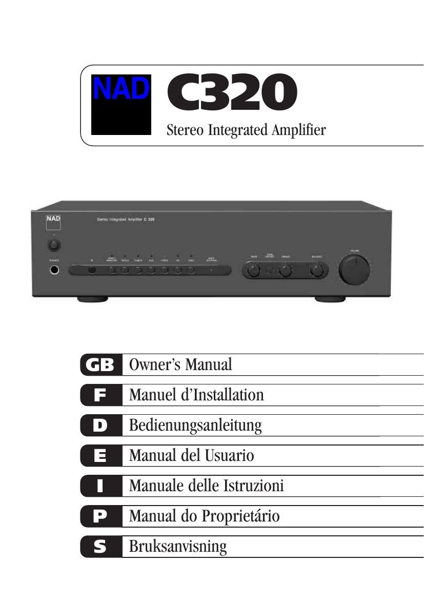
Nad C 320 Owners Manual

This is the 36 pages manual for Nad C 320 Owners Manual.
Read or download the pdf for free. If you want to contribute, please mail your pdfs to info@audioservicemanuals.com.

Page: 1 / 36
left right
Nad C 320 Owners Manual

Extracted text from Nad C 320 Owners Manual (Ocr-read)


Page 1

Warning: To reduce the risk of fire or electric shock, do not expose this unit to rain or moisture. The lightning flash with an arrowhead symbol within an equilateral triangle, is intended to alert the user to the presence of uninsulated Òdangerous voltageÓ within the productÕs enclosure that may be of sufficient magnitude to constitute a risk of electric shock to persons. The exclamation point within an equilateral triangle is intended to alert the user to the presence of important operating and maintenance (servicing) instructions in the literature accompanying the product. Do not place this unit on an unstable cart, stand or tripod, bracket or table. The unit may fall, causing serious injury to a child or adult and serious damage to the unit. Use only with a cart, stand, tripod, bracket or table recommended by the manufacturer or sold with the unit. Any mounting of the device on a wall or ceiling should follow the manufacturerÕs instructions and should use a mounting accessory recommended by the manufacturer. An appliance and cart combination should be moved with care. Quick stops, excessive force and uneven surfaces may cause the appliance and cart combination to overturn. Read and follow all the safety and operating instructions before connecting or using this unit. Retain this notice and the ownerÕs manual for future reference. All warnings on the unit and in its operating instructions should be adhered to. Do not use this unit near water; for example, near a bath tub, washbowl, kitchen sink, laundry tub, in a wet basement or near a swimming pool. The unit should be installed so that its location or position does not interfere with its proper ventilation. For example, it should not be situated on a bed, sofa, rug or similar surface that may block the ventilation openings; or placed in a built-in installation, such as a bookcase or cabinet, that may impede the flow of air through its ventilation openings. The unit should be situated from heat sources such as radiators, heat registers, stoves or other devices (including amplifiers) that produce heat. The unit should be connected to a power supply outlet only of the voltage and frequency marked on its rear panel. The power supply cord should be routed so that it is not likely to be walked on or pinched, especially near the plug, convenience receptacles, or where the cord exits from the unit. Unplug the unit from the wall outlet before cleaning. Never use benzine, thinner or other solvents for cleaning. Use only a soft damp cloth. The power supply cord of the unit should be unplugged from the wall outlet when it is to be unused for a long period of time. Care should be taken so that objects do not fall, and liquids are not spilled into the enclosure through any openings. This unit should be serviced by qualified service personnel when: A. The power cord or the plug has been damaged; or B. Objects have fallen, or liquid has been spilled into the unit; or C. The unit has been exposed to rain or liquids of any kind; or D. The unit does not appear to operate normally or exhibits a marked change in performance; or E. The device has been dropped or the enclosure damaged. DO NOT ATTEMPT SERVICING OF THIS UNIT YOURSELF. REFER SERVICING TO QUALIFIED SERVICE PERSONNEL Upon completion of any servicing or repairs, request the service shopÕs assurance that only Factory Authorized Replacement Parts with the same characteristics as the original parts have been used, and that the routine safety checks have been performed to guarantee that the equipment is in safe operating condition. REPLACEMENT WITH UNAUTHORIZED PARTS MAY RESULT IN FIRE, ELECTRIC SHOCK OR OTHER HAZARDS. ATTENTION POUR ƒVITER LES CHOC ELECTRIQUES, INTRODUIRE LA LAME LA PLUS LARGE DE LA FICHE DANS LA BORNE CORRESPONDANTE DE LA PRISE ET POUSSER JUSQUÕAU FOND. CAUTION TO PREVENT ELECTRIC SHOCK, MATCH WIDE BLADE OF PLUG TO WIDE SLOT FULLY INSERT. If an indoor antenna is used (either built into the set or installed separately), never allow any part of the antenna to touch the metal parts of other electrical appliances such as a lamp, TV set etc. CAUTION POWER LINES Any outdoor antenna must be located away from all power lines. OUTDOOR ANTENNA GROUNDING If an outside antenna is connected to your tuner or tuner- preamplifier, be sure the antenna system is grounded so as to provide some protection against voltage surges and built-up static charges. Article 810 of the National Electrical Code, ANSI/NFPA No. 70-1984, provides information with respect to proper grounding of the mast and supporting structure, grounding of the lead-in wire to an antenna discharge unit, size of grounding conductors, location of antenna discharge unit, connection to grounding electrodes and requirements for the grounding electrode. a. Use No. 10 AWG (5.3mm2) copper, No. 8 AWG (8.4mm2) aluminium, No. 17 AWG (1.0mm2) copper-clad steel or bronze wire, or larger, as a ground wire. b. Secure antenna lead-in and ground wires to house with stand-off insulators spaced from 4-6 feet (1.22 - 1.83 m) apart. c. Mount antenna discharge unit as close as possible to where lead- in enters house. d. Use jumper wire not smaller than No.6 AWG (13.3mm2) copper, or the equivalent, when a separate antenna-grounding electrode is used. see NEC Section 810-21 (j). EXAMPLE OF ANTENNA GROUNDING AS PER NATIONAL ELECTRICAL CODE INSTRUCTIONS CONTAINED IN ARTICLE 810 - RADIO AND TELEVISION EQUIPMENT. NOTE TO CATV SYSTEM INSTALLER:This reminder is provided to call the CATV system installerÕs attention to Article 820-40 of the National Electrical Code that provides guidelines for proper grounding and, in particular, specifies that the ground cable ground shall be connected to the grounding system of the building, as close to the point of cable entry as practical. CAUTION RISK OF ELECTRIC SHOCK DO NOT OPEN ATTENTION:RISQUE DE CHOC ELECTRIQUE NE PAS OUVRIR CAUTION:TO REDUCE THE RISK OF ELECTRIC SHOCK, DO NOT REMOVE COVER (OR BACK). NO USER SERVICEABLE PARTS INSIDE. REFER SERVICING TO QUALIFIED SERVICE PERSONNEL. IMPORTANT SAFETY INSTRUCTIONS 2

Page 2

3 FRONT PANEL CONTROLS REMOTE CONTROL REAR PANEL CONNECTIONS

Page 19

5. SELECTORES DE ENTRADA Estos pulsadores seleccionan la entrada activa al NAD C320 y la se-“al que se transmite a los altavoces, las salidas Tape y las tomas PRE OUT. Los pulsadores del control remoto duplican estos pulsadores, con excepci-n de entrada de sintonizador, vea a continuaci-n. Los diodos LED verdes que hay justo encima de cada pulsador indican quŽ entrada est-¡ seleccionada actualmente. DISC Selecciona una fuente de nivel de lnea conectada a las tomas DISC como entrada activa. CDSelecciona el CD (u otra fuente de nivel de lnea) conectado a las tomas CD como entrada activa. VIDEOSelecciona la VCR (o grabadora estŽreo de TV/SatŽlite/Cable) conectada a las tomas VIDEO como entrada activa. AUXSelecciona una fuente de nivel de lnea conectada a las tomas AUX como entrada activa. TUNER (sintonizador) Selecciona el sintonizador (u otra fuente de nivel de lnea) conectado a las tomas Tuner como entrada activa. El equipo manual de control remoto tiene pulsadores separados para AM y FM, pulsando uno de los dos se selecciona el sintonizador del C320. TAPE 2Selecciona Tape 2 como entrada activa. TAPE 1 Monitor Selecciona la salida de una grabadora de cintas cuando se escuchan cintas o controlan grabaciones que se est-¡n haciendo a travŽs de las tomas TAPE 1. Pulse el pulsador Tape 1 una vez para seleccionarlo y otra vez para volver a la selecci-n de entrada normal. Tape 1 es una funci-n de Monitor de cintas que no anula la selecci-n de entrada actual. Por ejemplo, si es entrada activa el CD cuando se selecciona TAPE 1, la se-“al CD continÅ“a seleccionada y se transmite tanto a las tomas TAPE 2, como a TAPE 1 OUTPUT, pero es el sonido procedente de la grabadora conectada a Tape 1 lo que se escuchar-¡ en los altavoces. Aparte del diodo LED -¡mbar que indica que Tape 1 est-¡ activada el diodo LED verde para la entrada activa tambiŽn est-¡ encendido. NOTA:El control remoto que se suministra con el C320 es tipo NAD universal dise-“ado para hacer funcionar varios modelos NAD. Algunos pulsadores de este equipo manual no funcionan porque sus funciones no tienen el soporte del C320. Los pulsadores selectores de entrada Vdeo 2 y Vdeo 3 del control remoto no funcionan en el caso del C320. 6. INDICADOR DE SOFT CLIPPING (RECORTE SUAVIZANTE) El diodo LED verde de Soft Clipping muestra que est-¡ activado el modo Soft Clipping. Vea tambiŽn el captulo Ã’Conexiones del Panel TraseroÓ, secci-n 12; Ã’Soft ClippingÓ para m-¡s informaci-n. 7. CONTROLES DE BASS Y TREBLE (BAJOS Y AGUDOS) El NAD C320 est-¡ equipado con controles de tono BASS y TREBLE para ajustar el equilibrio tonal de su sistema. La posici-n de las 12 horas es Ã-planaÕ sin refuerzo ni corte y hay un retŽn que indica esta posici-n. Gire el control a la derecha para aumentar la cantidad de Bass o Treble. Gire el control a la izquierda para disminuir la cantidad de Bass o Treble. Los controles de Tone (Tono) no afectan a las grabaciones hechas usando las salidas Tape pero afectan a las se-“ales que van a la salida Pre-amp (Pre-out).8. TONE DEFEAT (DESVêO DE TONO) El interruptor TONE DEFEAT desva la secci-n de control de tono del NAD C320. Si los Controles de Tone normalmente no se usan y se dejan en la posici-n de las 12 horas, es aconsejable quitar la secci-n de Control Tone totalmente usando este interruptor. En la posici-n Ã-outÕ (afuera), los circuitos de Control Tone est-¡n activos, si se empuja el interruptor TONE DEFEAT Ã-inÕ (adentro) se desva la secci-n de Control Tone. 9. BALANCE (EQUILIBRIO) El control BALANCE ajusta los niveles relativos de los altavoces de izquierda y derecha. La posici-n de las 12 horas da un nivel igual a los canales izquierdo y derecho. Hay un retŽn que indica esta posici-n. Si se gira el control a la derecha el equilibrio se mueve a la derecha. Si se gira el control a la izquierda el equilibrio se mueve a la izquierda. El control BALANCE no afecta a las grabaciones hechas usando las salidas Tape pero afecta a las se-“ales que van a la salida Pre-amp (pre-out). 10. VOLUME (VOLUMEN) El control VOLUME ajusta la altura general de las se-“ales que se alimentan a los altavoces, est-¡ accionado por motor elŽctrico y se puede ajustar desde el control remoto. El control VOLUME no afecta a las grabaciones hechas usando las salidas Tape pero afecta a las se-“ales que van a la salida Pre-amp (preamplificador) (Pre-Out). En el control remoto pulse el pulsador MUTE (silenciamiento) para desconectar temporalmente el sonido que va a los altavoces y auriculares. El modo de silenciamiento se indica con el diodo LED de entrada activa en intermitente. Pulse otra vez MUTE para restaurar el sonido. Mute no afecta a las grabaciones hechas usando las salidas Tape pero afecta a las se-“ales que van a la salida Pre-amp (Pre-out). PARA HACER UNA GRABACION Cuando se selecciona cualquier fuente de sonido, su se-“al se alimenta tambiŽn directamente a cualquier m-¡quina de cintas conectada a las salidas TAPE 2 o TAPE 1 OUTPUTS para grabaciones. COPIA DE CINTA A CINTA Usted puede copiar entre dos m-¡quinas de cintas conectadas con su NAD C320. Ponga la cinta fuente de sonido en la grabadora conectada a Tape 2 y la cinta que se va a grabar en la grabadora conectada a Tape 1. Seleccionando TAPE 2 Input usted puede ahora grabar desde Tape 2 a Tape 1 y vigilar la se-“al que procede de la cinta original. EQUIPO MANUAL DE CONTROL REMOTO El equipo manual de Control Remoto sirve para todas las funciones de tecla del NAD C320 y tiene controles adicionales para hacer funcionar remotamente Sintonizadores, m-¡quinas de cassettes y CD NAD. Funciona a una distancia de hasta 5 m. Para m-¡xima vida de servicio recomendamos pilas alcalinas. Deben colocarse dos pilas AAA (R 03) en el comportamiento de pilas situado en la parte trasera del equipo manual de Control Remoto. Al cambiar las pilas, compruebe que se hayan puesto en direcci-n correcta, como se indica en la base del compartimento de pilas. Rogamos consulte las secciones anteriores del manual para una descripci-n completa de las funciones individuales. NOTA: El equipo manual de control remoto que se suministra con el C320 es de tipo NAD universal, dise-“ado para hacer funcionar varios modelos NAD. Algunos pulsadores de este equipo manual de control remoto no funcionan porque las funciones no est-¡n soportadas por el C320. E 20