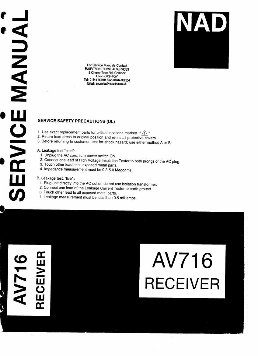
Nad AV 716 Service Manual

This is the 53 pages manual for Nad AV 716 Service Manual.
Read or download the pdf for free. If you want to contribute, please mail your pdfs to info@audioservicemanuals.com.

Page: 1 / 53
left right
Nad AV 716 Service Manual

Extracted text from Nad AV 716 Service Manual (Ocr-read)


Page 1

99

SERVICE MANUAL

For Service Manuals Contact
MAURITHON TECHNICAL SERVICES
3 Cherry Tree Rd, Chinnor
Oxon OX9 40!

Td: OIWSSIGM Fax:- 01844-352554
Emil: miflwmmonmm

SERVICE SAFETY PRECAUTIONS (UL)

1. Use exact replacement parts for critical locations marked A"
2. Return lead dress to original position and reinstall protective covers.
3. Before returning to customer, test for shock hazard; use either mothod A or B;

A. Leakage lest cold":
1. Unplug the AC cord; turn power switch ON.
2. Connect one lead of High Voltage Insulation Tester to both prongs of the AC plug.
3. Touch other lead to all exposed metal parts.
4. impedance measurement must be 0.3-5.0 Megohms.

B. Leakage test, live" :
1. Plug unit directly into the AC outlet: do not use isolation transformer.
2. Connect one lead of the Leakage Current Tester to earth ground.
3. Touch other lead to all exposed metal parts.
4. Leakage measurement must be less than 0.5 milliamps.

AV716
RECEIVER

n:
I.l.I
2
NJ
0
LIJ
n:

Page 2

SERVICE SAFETY PRECAUTIONS

1. Replacing the fuses

This symbol located near the fuse
{ - indicates that the fuse used is fast
operating type. For continued protection against fire hazard,
replace with same type fuse. For fuse rating refer to the
marking adjacent to the symbol.

Circuit No. Part No. Description
F901 252166Y 6.3A-ULff-237, Primary

F902 252076 or 3.15A-SE-EAK, Primary
252076Y
F903 252075 or 2.5A-SEvEAK, AC outlet
252075Y
F911 252166Y 6.3A-ULff-237, Secondary

252079 6.3A-SE-EAK, Secondary

F912 252166Y 6.3A-UL/T-237, Secondary

252079 6.3A-SE-EAK, Secondary

NOTE: : USA, Canadian model only
: UK. model only
: Australian model only
<0: European model only

2. Memory preservation

This unit does not require memory preservation batteries

A built-in memory power back-up system preserves contents
of the memory during power failures and even when the unit
is unplugged. The unit must be plugged in and the power
switch tumed on and off once in order to charge the back-up
system. Note that since this is not a permanent memory the
power switch must be turned on and off a few times each
month to keep the backup system operative. The period of
time during which memory contents are preserved after power
has last been turned off varies depending on climate and
placement of the unit. On average, memory contents are
protected over a period of 3 to 4 weeks (a minimum of 2
weeks) after the last time power has been turned off. This
period is shorter when the unit is exposed to very high
humindity or used in an area with an extremely humid
climate.

3. Safety~check out

(Only U.S.A. model)

After correcting the original service problem perform the
following safety check before releasing the set to the
customer.

Connect the insulating-resistance tester between the plug of
power supply cord and the screw on the back panel.
Specifications : 3.3 Mohmi 10% at 500V.

For Service Manuals Comm
MAURITRON TECHNICAL SERVICES
8 Cherry Tree Rd, Chinnor

Oxon 0X9 4OY

Tetr- 01044-351694 Fax:- 0134445554
Enuilz- mammal:

5

Q

Page 16

in No. Symbol Description
1 VSS Ground terminal
2 EN Chip enable input mind. Connect to the terminal EN of
the microprocessor.
3 m Latch input terminal. Connect to the terminal LAT of the
microprocessor.
4 SO Serial data output terminIlNot used.
5 a Not used.
6 67 Not used.
7 0'? Front speaker relay control output terminal
8 a Center speaker relay control output terminal
9 0-4 Rear Speakfl relay control terminal
lo 63 Remote speaker relay control terminal
ll 0-2- Headphone relay control output terminal
l2 6 Power supply voltnxe switch relay control output terminal
13 SIN Serial data input terminal. Canneet to the terminal DATA
of the microprocessor.
14 SCK Serial clock input terminal. Connect to the terminal CLOCK
of the micropromsor.
15 RESET Reset input terminal
16 VDD Power supply terminal
8 Cherry Tree Rd. Chinnor
Oxon OX9 4OY
sz-o1w-35l894 Fax2- 01844-352554
a. a. a. o. a. Emailz- memumwm

Pa

Pa

Pa

S)

$4

sa :1 a. -Oso

:Iu-It

mm mm")

19

BLOCK DIAGRAMS

AMPLIFIER SECTION

aurrur

mm

1

nun um.

i . . . .

2 5 M 070 «a ,
1 L Eli!

um
mac:
$ 1

l 3 t;
l"
1
Mr r;
n. .. x, 95,. ~ It:
. 5i= $2 s§= $2 u 5??
$2? $2? 2%? ,
j :2 E ;;
£§ ng-L 330-
r.
l
21: 4 A}? 3
§§4tm .___:"t_:\c__ 9t; . E.
91 I 1 :35
3 u§§ _
. . T $ .-
s E
T T
E s x :

?

nan)
nutter

..
.
u

Harman 1.1le Human u:

:
S
aaaaa a:

I; mu. Fol an sauna

(

a lot

t»:
up: 1
men