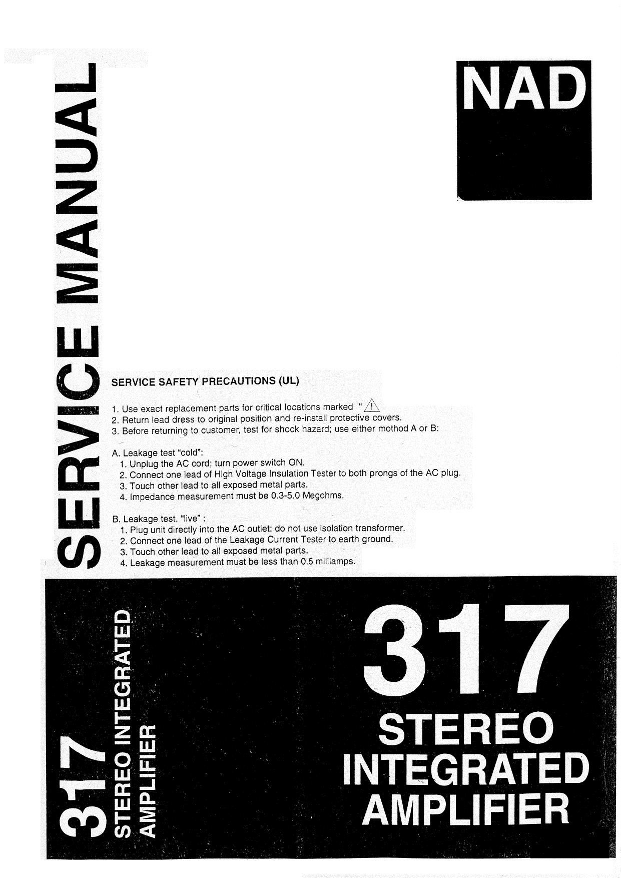
Nad 317 Service Manual

This is the 22 pages manual for Nad 317 Service Manual.
Read or download the pdf for free. If you want to contribute, please mail your pdfs to info@audioservicemanuals.com.

Page: 1 / 22
left right
Nad 317 Service Manual

Extracted text from Nad 317 Service Manual (Ocr-read)


Page 1

V

SERVICE MANUAL

STEREO INTEGRATED,

SERVICE SAFETY PRECAUTIONS (UL)

.Use exact replacement parts for critical locations marked L\
2 Return lead dress to original position and re- -install protective covers.
3. Before returning to customer, test for shock hazard; use either method A or B:

A. Leakage test cold":
1, Unplug the AC cord; turn power switch ON.
2. Connect one lead of High Voltage Insulation Tester to both prongs of the AC plug.
3. Touch other lead to all exposed metal parts.
4. Impedance measurement must be 0.3-5.0 Megohms.
B. Leakage test. live" :

1. Plug unit directly into the AC outlet: do not use isolation transformer.
2. Connect one lead of the Leakage Current Tester to earth ground.

3. Touch other lead to all exposed metal parts,

STEREO
INTEGRATED
AMPLIFIER

n:
I_.I_J
Eh
_I
n.
E
F

Page 2

SERWCESAFETYPRECAUHONS

1. Replacing the fuses

I:i:i"" This symbol located near the fuse indicates that the fuse used is fast operatin
type. For continued protection against fire hazard, replace with same type fuse. Fc
fuse rating refer to the marking adjacent to the symbol.

Reference No Part Number Description

FSOI'AH N51007030v1A Fuse 7A 125V Time Lag LBC (UUCSA)

F501B.C N51002530~1 B Fuse 2.5A 250V Time Lag LBC (SEMKO/VDE)
FSDZ'AH 5120-0036-0 Fuse iOOmA 250V Medium Time Lag LBC (UUCSA)
F502B,C 5120-0035-0 Fuse 100mA 250V Time Lag LBC (SEMKONDE)
NOTE :

- : USA, CANADIAN MODEL ONLY.
: UK MODEL ONLY.
<'C > : EUROPEAN MODEL ONLY.

2. Safety-check out

(Only U.S.A. model)

After correcting the original service problem perform the following safety check before releasin
the set to the customer.

Connect the insulating-resistance tester between the plug of power supply cord and the screw 0
the back panel.

Specifications : 3.3 Mohm:10% at 500V.

CONTENTS

DESCRIPTION PAGE
SPECIFICATIONS ....................................................................................................................... 4-5
REAR PANEL l FRONT PANEL VIEW ................................. 6
WIRING DIAGRAM ..................................................................................................................... 7-3
DISASSEMBLY INSTRUCTIONS ................................................................................................... 9
ALIGNMENT POINTS DIAGRAM I PROCEDURE ........................... 10
PCB LAYOUT .......................................................................................................................... 11-13
SCHEMATIC DIAGRAM .......................................................................................................... 14-19
IC BLOCK DIAGRAM . ....................................... 20-21
EXPLODED VIEW ......................................... . .............................................................................. 22
EXPLODED VIEW PARTS LIST ............................................................................................. 23-24
ELECTRICAL PARTS LIST .. .................................................................................. 25-30
PACKING DIAGRAM I PACKING LIST.... ..................................................................................... 31

Page 20

PACKING DIAGRAM

PACKING LIST

llgm Part No Description Q1
1 1490-20934 POLYFOAM END CAP 2
2 N14971072~3 UNIT POLYBAG 1
3 N14971252-0 FASCIA COVER 1
4 4301-3669-0 INSTRUCTION MANUAL 1
5 1476-5201-0 CARTON BOX 1
6 4060-0580-0 BATTERIES 2
7 8900-1070-0 REMOTE CONTROL 1
8 N14971062-0 MANUAL POLYBAG 1

31