Nad 214 Service Manual

This is the 15 pages manual for Nad 214 Service Manual.
Read or download the pdf for free. If you want to contribute, please mail your pdfs to info@audioservicemanuals.com.

Page: 1 / 15
left right
Nad 214 Service Manual

Extracted text from Nad 214 Service Manual (Ocr-read)


Page 1

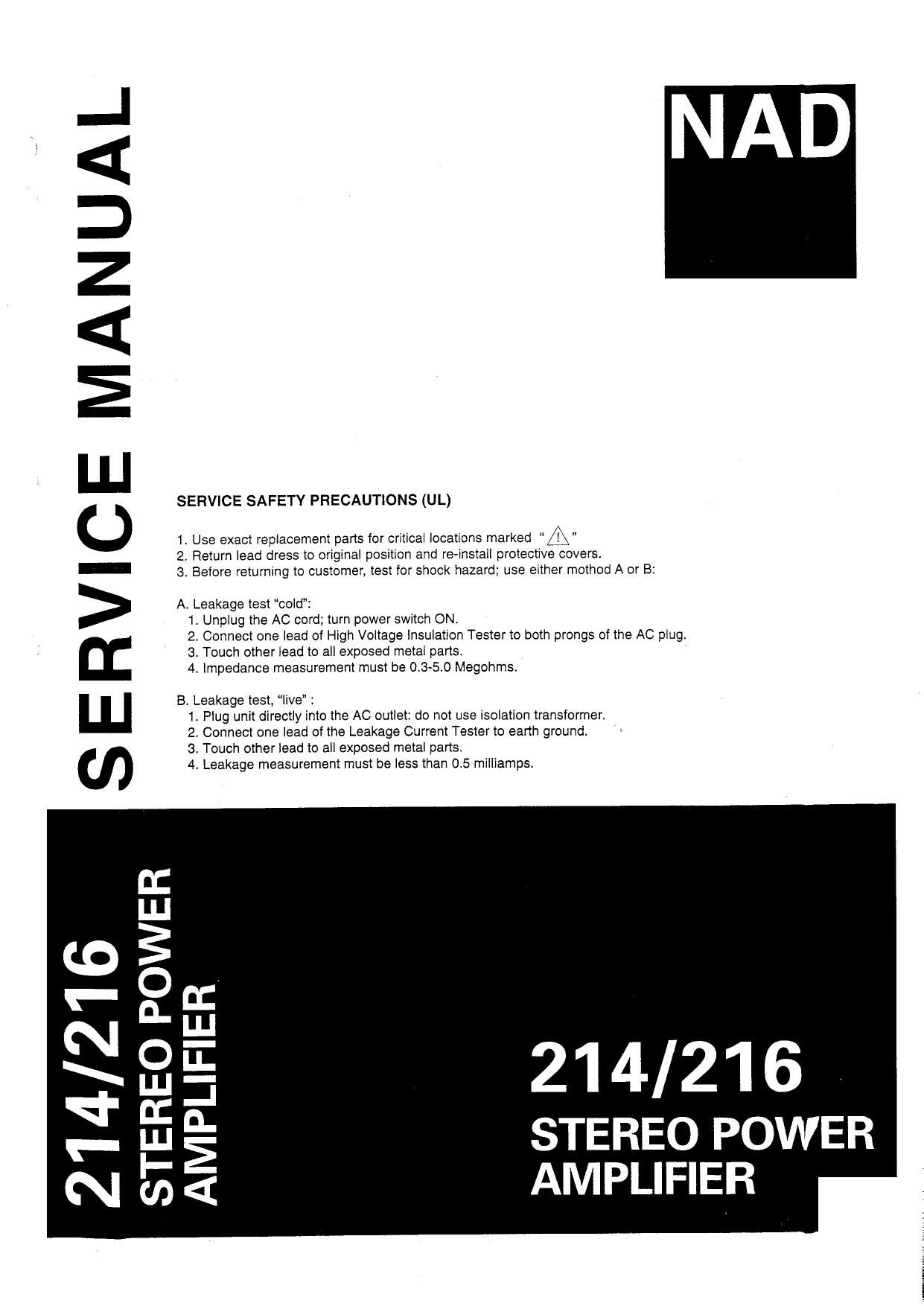
SERVICE SAFETY PRECAUTIONS (UL)

. . I /\
1 Use exact replacement parts for critical locations marked "1!) "
2, Return lead dress to original position and re-install protective covers.
3. Before returning to customer, test for shock hazard; use either method A or B:

A, Leakage test cold":
1. Unplug the AC cord; turn power switch ON
2. Connect one lead of High Voltage insulation Tester to both prongs of the AC plug
3. Touch other lead to all exposed metal parts.
4. Impedance measurement must be 0.3-5.0 Megohms.

B. Leakage test, live :
1. Plug unit directly into the AC outlet: do not use isolation transformert
2. Connect one lead of the Leakage Current Tester to earth ground.
3. Touch other lead to all exposed metal parts.
4. Leakage measurement must be less than 05 milliamps.

SERVICE MANUAL

214/216

STEREO POWER
AMPLIFIER

D:
I.
3
O
n.
O
|.l.l
D:
LLI
l-
(D

to_
E
Q:
w:
P

N

Page 2

TABLE OF CONTENTS

SPECIFICATIONS .................................. 3
REAR PANEL ..................................... 4
FRONT PANEL .................................... 4
PCB LAYOUT ..................................... 5
EXPLODED VIEW PARTS LIST --------------------------- 6
EXPLODED VIEW .................................. 7
WIRING DIAGRAM ................................. 8
SCHEMATIC DIAGRAMS

214 ...................................... 9

216 ...................................... 1O
ELECTRICAL PARTS LIST ............................. 11
ALIGNMENT PROCEDURE ---------------------------- 14
PACKING DIAGRAM ................................. 15

NOTE: The '",A given after an item number, refers to the part number for the modet 216 only.

é
a
r

Page 8

WIRING DIAGRAM

Speaker

Grn

Power Supply

soldered
(0 Tab on
Subchassis

{-1 I

JPSOI


Right W. Left
Channel Channel
Legend:
Blu - Blue
Blk - Black
Brn - Brown
Grn - Green
Gry - Grey
Org - Orange _ _ _ L
Red - Red I-_ j I- -I
Vio - Violet
wm - White Power I I I I
Transformer
Note: All PCBs are shown copper side. M . l M . I
alns OII'IS
AH Version C Verslon
L L L L L L L _ _I L. ______ L J

Page 14

ALIGNMENT PROCEDURE

EQUIPMENT

Digital voltmeter (DVM) switched to 200mV DC range.

TEST CONDITIONS

Ensure VR301 and VR302 are set to minimum (fully counterclockwise) before first switching on

Preheat Minimum five (5) minutes

Load No load \

Input No signal I
ALIGNMENT

Connect DVM across TP301 and TP303, Left Channel.
2. Adjust VFI801, Left channel, fora reading of:
214 20mV :1.5mV.
216 18mV :1.5mV.
3. Connect DVM across TP802 and TP304, Right channel.
4. Adjust VR302. Right channel, for a reading of:
214 20 mV 11.5mV.
216 18mV 11.5mV.
Leave power on for a further five (5) minutes (minimum).
6. Repeat steps 1 to 4.

_.

E"

Left Channel Right Channel

IIIWIWM

rpso;
E . Tplm
E
TPSOI
E
TPJoz '
El
lDLE lDLE
CURRENT CURRENT
VRsoi VR302 g

Mlllllllllmlllllllfl

ll

AMPLIFIER ADJUSTMENT POINTS

14

Page 15

PACKING DIAGRAM

lTElll PART NUMBER NAME on!
52 Unit 1
53 N14971252-0 EPE Bag (214) 1
53 A N14971162-0 EPE Bag (216) 1
54 N14971072-3 Polybag Unit 1
55 N4901583-0 Polyfoam (214) 2
55 A N4901643-0 Polyioam (216) 2
56 N43013535-0 Instruction Manual 1
57 AH N303010572 Salety Instruction Sheet (AH) 1
58 AH N30301056-0 Warranty Card (AH) 1
59 N14971062-0 Polybag Manual 1
60 N14761401-O Gift Box (214) 1
60 A N14761600-0 Gift Box (216) 1

Proprietary information for servicing purposes only.

15

The information herein may not be used
commercially without the prior written agreement of NAD Electronics Ltd., London, England.