Musical fidelity xp 200 owners manual

This is the 4 pages manual for musical fidelity xp 200 owners manual.
Read or download the pdf for free. If you want to contribute, please mail your pdfs to info@audioservicemanuals.com.

Page: 1 / 4
left right
musical fidelity xp 200 owners manual

Extracted text from musical fidelity xp 200 owners manual (Ocr-read)


Page 1

IMPORTANT! (U.K. only) This unit is supplied in the U.K. with a mains lead fitted with a moulded 13 amp plug. If, for any reason, you need to cut off this plug, please remove the fuse holder and dispose of the plug safely, out of reach of children. It must not be plugged into a mains outlet . The wires in the mains lead supplied with this appliance are coloured in accordance with the following code: Green and yellow..............Earth Blue...............................Neutral Brown................................Live W ARNING - This appliance must be ear thed As the colours of the wires of the mains lead of this appliance may not correspond with the coloured markings identifying the terminals in your plug, proceed as follows: The wire which is coloured green-and-yellow must be connected to the terminal in the plug which is marked with the letter E or coloured green or green-and-yellow, or by the earth symbol: The wire which is coloured brown must be connected to the terminal which is marked with the letter L or coloured red. The wire which is coloured blue must be connected to the terminal which is marked with the letter N or coloured black. If connecting to a BS1363 plug, a 13 amp fuse must be used. SAFETY INFORMATION X-P200 Power Amplifier Page 7 of 7 Page 2 of 7 X-P200 Power Amplifier WARNING : Any modifications to this product not expressly approved by Musical Fidelity who is the party responsible for standards compliance could void the users authority to operate this equipment. Your new X-P200 is designed and built to provide trouble-free performance, but as with all electronic devices, it is necessary to observe a few precautions : -˛Do not use the X-P200 near water. The unit must not be exposed to dripping or splash ing and no objects filled with liquids, such as vases, must be placed on the unit. -˛Keep the X-P200 away from heat such as radiators. No naked flame sources, such as lighted candles, should be placed on the unit. -˛Place all connecting cables where they are not likely to be walked on or trapped by items placed on them. Output : Power, stereo mode : 125 Watts, one channel loaded into 8 Ohms (21dBW) Power, bridge mode : 260 Watts into 8 Ohms (24dBW) Voltage RMS, stereo mode : 31.6 Volts 20Hz to 20kHz, one channel loaded Voltage peak, stereo mode : 44.5 Volts, one channel loaded Current peak-to-peak (unlimited) : 75 Amps Damping factor, stereo mode : 200 Output devices per channel : 4 (stereo), 8 (bridge) Line inputs : Total harmonic distortion + noise : < 0.015 20Hz to 20kHz Signal / noise ratio : > 107dB A-weighted Input sensitivity for 125W, 8 Ohms : 1 Volt Input impedance : 27k Ohms in stereo mode, 220k Ohms bridge mode Channel separation : > 70dB typical Frequency response : 20Hz to 20kHz, + 0, - 0.1dB Input facilities : A 1 pair RCA connectors, selectable from front panel B 1 pair RCA connectors, selectable from front panel Output facilities : 2 amplifier channels or 1 channel in bridge mode (switchable from front panel) via 1 pair per channel binding posts. 1 pair RCA loop output sockets Power requirement : 100 / 115 / 230Volts AC 50 / 60Hz (factory pre-set), 600 Watts maximum (bridge mode) into 8 Ohms, 30 Watts idle. Dimensions : 218mm, 8.6 inches wide 98mm, 3.8 inches high (including feet) 339mm, 13.4 inches deep (including knob and rear terminals) Weight : 6.1 kg, 13.4 lbs unit only, unboxed 7.15 kg, 15.8 lbs in shipping carton Standard accessories : IEC type mains lead (10-Amp type) Musical Fidelity reserves the right to make improvements which may result in specification or feature changes without notice. X-P200 SPECIFICATIONS

Page 2

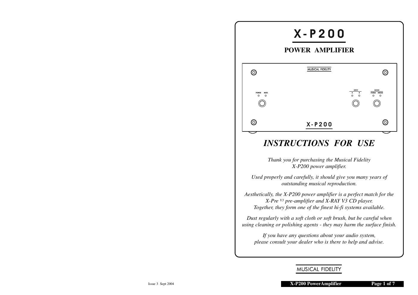
X-P200 Power Amplifier Page 3 of 7 Page 6 of 7 X-P200 Power Amplifier INTRODUCTION Your X-P200 can be connected either as a conventional stereo amplifier, or alternatively in bridge mode as a mono amplifier with higher output power - see page 4 and 5 for connection details. It is intended for use with a pre-amplifier or similar audio level source with a volume control. We highly recommend the matching X-Pre preamplifier also available from Musical Fidelity. Two stereo pairs of RCA audio input sockets marked A and B on the rear panel allow a choice between either of these input sources. Simultaneous mixed A and Boperation is not possible. Whichever input is chosen, a fixed line level audio output from the selected source is available from the adjacent OUTPUTRCA sockets for onward connection to another amplifier. This is to allow for bi-amplification (see below). BI-AMPLIFICA TION The X-P200s OUTPUTsockets allow bi- amplification of a speaker system using suitable external amplifiers and crossover networks. This enables the speaker drive units to be powered separately, giving noticeable improvement in clarity, imaging and bass weight. In this arrangement, typically one X-P200 is used to drive the tweeter (high frequencies), and another to drive the woofer (low frequencies) of each loudspeaker enclosure. Thus, two X-P200s would be needed for a stereo pair, or four in bridge mode. (continued) . . . If in doubt about bi-amplification, please contact your dealer for advice. BEFORE SWITCHING ON . . . . Plug the accessory IEC mains lead into the rear panel socket, then the other end into a wall outlet. Turn the volume control on your pre- amplifier to minimum. OPERA TION Press the POWERbutton on the X-P200 amplifier - the blue power LED on the front panel will light indicating that the unit is ready for use. However, for about six seconds no sound will be heard from your speakers, and the red mute LED will be lit, confirming initial mute action. Press the INPUTselector button on the front panel to switch between Aand Binput as required. A corresponding blue LED above the button will light to confirm your selection. Now adjust the volume control on your pre- amplifier to obtain the preferred sound level. If bridge loudspeaker operation is required, press the MODEbutton on the front panel to switch over to this function. A corresponding blue LED above the button will light to indicate which system is in use. Press the MODEbutton again to revert to normal stereo. Please note that if STEREOmode is accidently selected with the speakers wired for bridge operation, sound will be distorted, and lack bass. Similarly, if switched to BRIDGEmode with speakers wired for stereo operation, sound quality will OPERATION FACILITIES (see page 6) X- P 20 0 MODE INPUT Power indicator LED (blue) Power on/off push- button switch Loudspeaker mode push-button switch Input mode push-button switch Mute indicator LED (red) Input indicator LEDs (blue) Loudspeaker mode indicator LEDs (blue)