Motorola xp 254 e service manual

This is the 8 pages manual for motorola xp 254 e service manual.
Read or download the pdf for free. If you want to contribute, please mail your pdfs to info@audioservicemanuals.com.

Page: 1 / 8
left right
motorola xp 254 e service manual

Extracted text from motorola xp 254 e service manual (Ocr-read)


Page 1

SUPPLEMENT NO. 2
TO TS-460 SERVICE MANUAL ,
PART NO. 68P65135A84

COVERS
CHASSISACODED
A 08 THRU B 00

SUPPLEMENT NO. 2
TO T3460 SERVICE MANUAL,
PART No. 68P65135A84

COVERS
CHASSIS CODED
A708 THRU B-DO

television

MOTOROLA

GENERAL
INFORMATION

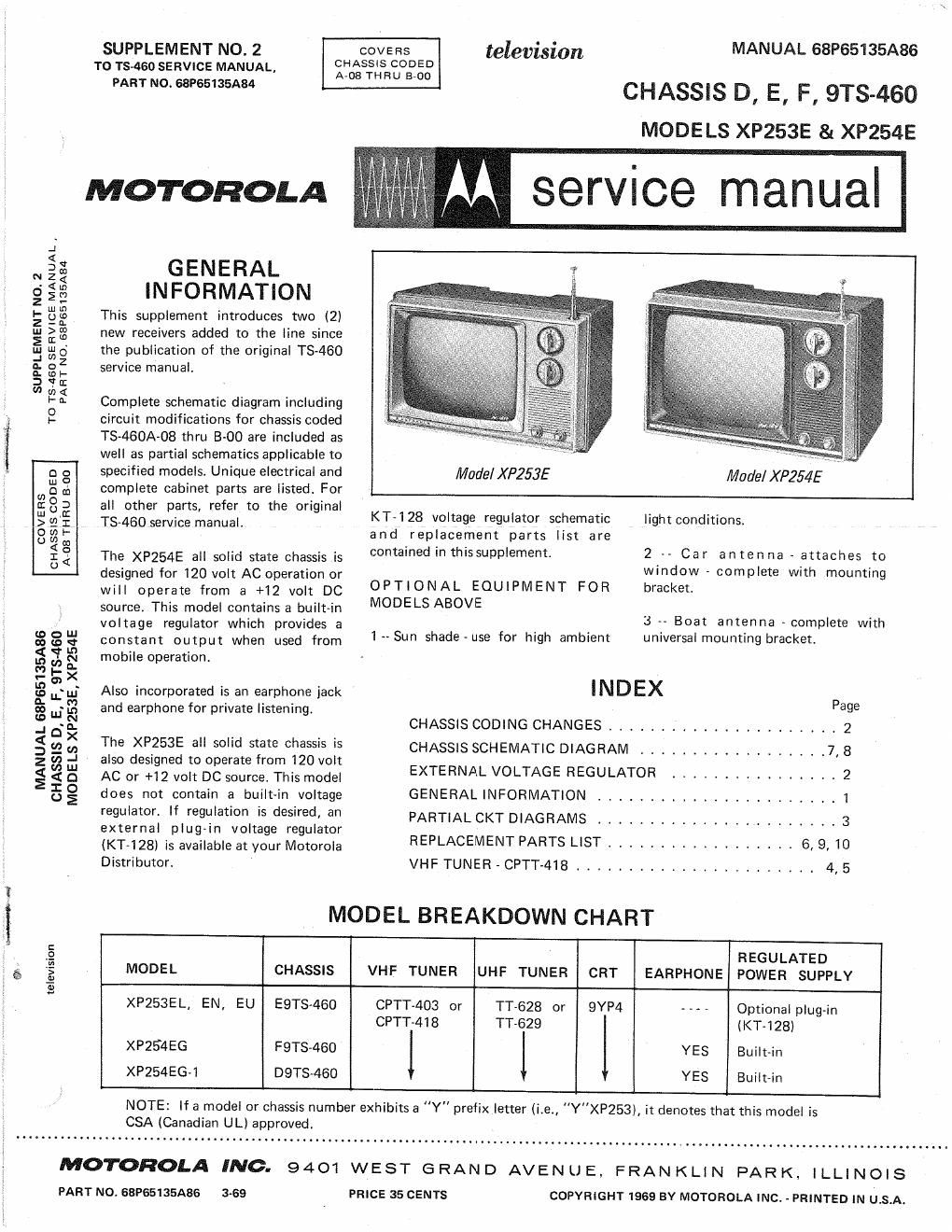
This supplement introduces two (2)
new receivers added to the line since
the publication of the original TS-460
service manual.

Complete schematic diagram including
circuit modifications for chassis coded
TS-460A-08 thru 8-00 are included as
well as partial schematics applicable to
specified models. Unique electrical and
complete cabinet parts are listed. For
all other parts, refer to the original
TSASOservjce manual.

The XP254E all solid state chassis is
designed for 120 volt AC operation or
will operate from a +12 volt DC
source. This model contains a built~in
voltage regulator which provides a


MANUAL 68P65I35A86

CHASSIS D, E, F, 9TS-460
MODELS XP253E 8t XP254E

service manual

Model XP253E

Model XP254E LL

KT-7128 voltage regulator schematic
and replacement parts list are
contained in this supplement.

OPTIONAL EQUIPMENT FOR
MODELSABOVE

light conditions.

2 -» Car antenna -
window -
bracket.

attaches to
complete with mounting

3 A» Boat antenna - complete with

0% 8 g Constant output when used from 1 «~ Sun shade -use for high ambient universal mounting bracket.
% T R mobile operation.
to {2 §
-
g Eu; Also incorporated is an earphone jack INDEX P
% ":3 and earphone for private listening. age
, S d: CHASSIS CODING CHANGES ...................... 2
i g u: :2 The XP253E 3 solid state chassis is CHASSIS SCHEMATIC DIAGRAM .................. 7, 8
z :7) -J also designed to operate from 120 volt
g g UQJ AC or +12 volt DC source. This model EXTERNAL VOLTAGE REGULATOR ................ 2
5 g does not contain a built-in voltage GENERAL INFORMATION ....................... 1
regulatofi regulatim is desired, 8" PARTIAL CKT DIAGRAMS ..................... 3
external plug-in voltage regulator ' '
(KT<128I is available at your Motorola REPLACEMENT PARTS LIST .................. 6, 9,10
Distributor. VHF TUNER - CPTT-418 ....................... 4, 5
MODEL BREAKDOWN CHART
é REGULATED
3 MODEL CHASSIS VHF TUNER UHF TUNER CRT EARPHONE POWER SUPPLY
.-
XP253EL, EN, EU E9TS-460 CPTT-403 or TT-628 or 9YP4 - »- . Optional plug-in
, CPTT-4I 8 TT-629 (KT-128)
i. XP254EG F9TS-460 YES Bui|t~in
XP254EG-I D9T8v460 YES Built-in

NOTE: If a model or chassis number exhibits a "Y" prefix letter (i,e., "Y"XP253), it denotes that this model is
CSA (Canadian UL) approved.

MOTOROLA INC. 9401 WEST GRAND AVENUE, FRANKLIN PARK. ILLINOIS

PART NO. 68P65I35A86 3-69 PRICE 35 CENTS COPYRIGHT 1969 BY MOTOROLA INC. - PRINTED IN USA.

Page 2

CHASSIS CODING CHANGES

Chassis Coding Chassis Coding Changes
9TS~460A-08 TO IMPROVE VIDEO BIAS RANGE: R116, IK, /2 watt resistor changed to 1.5K, 1A: watt
resistor.
9TS-460A-09 DESIGN CHANGE: To decrease horizontal width, choke added to flyback terminal board -
see schematic for circuit
9TS-460A40 TO IMPROVE VIDEO DETA|L: R202 (220K) replaced with 33K, V2 watt resistor. C202 (.DII
replaced with .05.
QTS-460A-ll DESIGN CHANGE: To reduce horizontal frequency drift, 0506 (.01) replaced with a special
.01, Part No. BS10191A354
QTS-460A-12 RELIABILITY CHANGE: T501 flyback transformer replaced with Part No. 24DG7561A05
and a 1X23 high voltage rectifier tube.
RELIABILITY CHANGE: Vertical output choke L600 replaced with Part No. 25067554A13.
QTS»46(JB-OO DESIGN CHANGE: 012 audio driver (M4842) omitted from circuit ~ see schematic for
change.
DESIGN CHANGE: Horizontal driver circuit - see schematic for change.
+
INPUT
FROM BATTERY

12,3V
V OUTPUT

NOTE: WHEN REPAIR IS NECESSARY AND PARTS ARE REPLACED, IT IS
RECOMMENDED THAT THE UNIT BE ADJUSTED TO REGULATE
AT 12.3V OUTPUT WITH AN INPUT VOLTAGE OF 135 VOLTS.

:4 an

Schematic Diagram - External Voltage Regulator - K T- 728


R5 I12 33 E1
ZEHER

III

(II
MOUNTEII
Ulll REVERSE

SIDE

RE
REE ULATO H
ADJUSTMENT

Parts Location - External Valtage Regulator K T- 723 (Part No. 7 V65534A6'0)

2