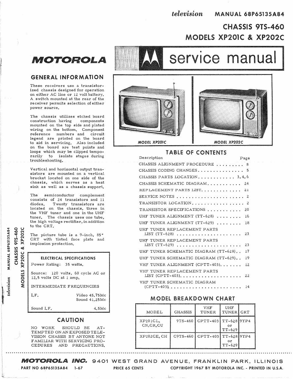
Motorola xp 201 c service manual

This is the 24 pages manual for motorola xp 201 c service manual.
Read or download the pdf for free. If you want to contribute, please mail your pdfs to info@audioservicemanuals.com.

Page: 1 / 24
left right
motorola xp 201 c service manual

Extracted text from motorola xp 201 c service manual (Ocr-read)


Page 1

television MANUAL 68P65135A84

CHASSIS 9TS-460
MODELS XP2OIC & XP202C

mow-anon M service manual

GENERAL INFORMATION

These receivers use a transistor-
ized chassis designed for operation
, on either AC line or 12 volt battery.
; A switch mounted at the rear of the
receiver permits selection ofeither
power source.

The chassis utilizes etched board
construction having Components
mounted on the top side and plated
wiring on the bottom. Component
reference numbers and circuit
legend are printed On the board

to aid in servicing. Also included MODEL XPZOIC MODEL XP202C

on the board are test points and

loops which may be clipped tempo- TABLE OF CONTENTS

rarily to isolate sta es durin . ,

troubleshooting. g g Derscriprtion Page
V CHASSIS ALIGNMENT PROCEDURE . . . . . . . . . 8
- Vertical and horizontal output tren- CHASSIS CODING CHANGES. . . . . . . . . . . . . . . 5
sisters are mounted on a vertical
bracket located on one side of the CHASSIS PARTS LOCATION. . . . . . . . . . . . 3,436

ehessie- which serves as a heat CHASSIS SCHEMATIC DIAGRAM. . . . . . . . . . . 24

sink as well as a chassis support.

REPLACEMENT PARTS LIST ........ . . . . . 21
The semiconductor complement SERVICE NOTES . . . . . . . . . . . . . . . . . . . . . . 2
consists of 24 transistors and 11
diodes. Twenty transistors are TRANSISTOR LOCATION ..... I . . . . . . . . . . . z
heated 0 the eheeeie: three in TRANSISTOR SPECIFICATIONS I . . . . . . . . . . 20
the VHF tuner and one in the UHF
men The Chassis uses one tube, UHF TUNER ALIGNMENT (TT-szs) . . . . . . . . 16
the high voltage rectifier,inaddition UHF TUNER ALIGNMENT (TT-6Z9) . . . . 18
to the CRT. '
; g g g UHF TUNER REPLACEMENT PARTS
g q; a The picture tube is a 941mm 85' LIST (Tr-628) . . . . . . . . . . . . . . . . . 23
a g a a. CRT with tinted face Plate and UHF TUNER REPLACEMENT PARTS
E a : 1mP1°510nProtectiom LIST (TT-629) . . . . . . . . . . . . . . . .. . I .. 23
j a u UHF TUNER SCHEMATIC DIAGRAM (TT-628). . 17
g § § ELECTRICAL SPECIFICATIONS UHF TUNER SCI-LEMATIC DIAGRAM (IT-629). . 19
z .
< U g Power Rating: 35 watts. VHF TUNER ALIGNMENT (CPTT-403). . . . . . . 12
E
E Source: 120 volts, 60 cycle AC or VHLES'I'IUEERTiiPSSACEMENT PARTb 22
g o 12.5v0n5DCatlamP. -
.2 O VHF TUNER SCHEMATIC DIAGRAM
g E INTERMEDIATE FREQUENCIES (CPTT-403). . . . . . . . . . . . . . . . . . . . . . . . 14
Q
~
N ,
vs LF. Video 45.75Mc
Sound 41.25Mc MODEL BREAKDOWN CHART
Sound LF, 4.5Mc VHF UHF
MODEL CHASSIS TUNER TUNER CRT
. CAUTION XPZOICL, 9TS-460 CPTT-403 TT-ézs 9YP4
No WORK SHOULD BE AT- CNCRCU T1322?
, TEMPTED ONANEXPOSEDTELE-
:_ VISION CHASSIS BY ANYONE NOT XPZOZCE, CH C9TS-460 CPTT-403 TT-628 9YP4
_ FAMILIAR WITH SERVICING PRO- or
CEDURES AND PRECAUTIONS. TT-62-9

MOTOROLA INC. 9401 WEST e RAN D AVEN u E, FRAN KLI N PAR K, ILLINOIS
PART NO 68P65135A84 1-67 PRICE 65 CENTS COPYRIGHT 1967 BY MOTOROLA INC. - PRINTED IN U.s.AI

Page 2

SERVICE NOTES
ETCHED BOARD CIRCUIT TRACING

The top (component side) of the
chassis board contains a complete
legend of the chassis circuit that
appears on the bottom and identifi-
cation of all components by refer-
ence numbers that are related to
the reference numbers on the sche-
matic diagram. The circuit may be
traced from the top of the chassis
board and all components can be
identified eliminating the need of
making any reference to the bottom
of the chassis board.

The circuit side (bottom) of the
chassis board also contains a com-
plete legend which includes compo-
nent reference numbers, transistor
identification, coil terminals and
the wiring (jumper wires) is traced
in to provide easy circuit tracing
of the wiring that appears on the top
side of the chassis board.

The transistors are identified by
their function as well as the refer-
ence number. The transistor ele-
ments are identified as follows:
E - emitter, B - base and C - col-
lector.

The tracing indicates where the
wiring (jumper wires) on the top of
the chassis board is connected.

Breaks appear in the wire tracing
to facilitate the identification of
components location, Each wire
trace begins and ends with an arrow
to indicate where it begins and ends.

To further facilitate circuit tracing
of the etched chassis board, aphoto-
graph of the chassis board with the
pertinent test points identified and
related to the schematic diagram is
included in this manual.

VHF TUNER PIC
TRANS IISTORS AGO AMP
INS

05C


lST IF AMP

UHF TUNER
TRANSISTOR INSIDE

IST VIDEO AMP

The test points on the schematic
diagram are identified descriptively
and/or by number and are blocked
in or circled for easyidentification.
These test points are also shown on
the chassis board photographs and
serve to pinpoint the physical loca-
tion of the electrical junction or test
point of interest.

All other test points may be easily
located by circuit tracing from a
transistor, coil, etc. or any point
that is readily identified.

CHASSIS REMOVAL

Refer to receiver parts location
photo. Five (5) screws secure the
chassis to the cabinet, They are
located as follows: one (1) at the
upper left corner, two (2) at lower
left and two (2) at the right side.

COMPONENT REMOVAL

Removing components from the
etched board is facilitated by the
fact that the circuitry (plating) ap-
pears on one side of the board only
and the component leads are in<
serted straight throughthe holes and
are not bent or crimped.

It is recommended that a solder ex-
tracting gun he used to aid in com--
ponent removal. An iron with a
temperature controlled heating ele-
ment would be desirable since it
would reduce the possibility ofdam-
aging the board due to over-heating,

The nozzle of the soldering gun is
inserted directly over the compo-
nent lead and when sufficiently
heated, the solder is drawn away
leaving the lead free from the copper
plating, This methodis particularly
suitable in removing multi-terminal
components.

WM M4732

Plc NW
RF Aoc AMP mm: was ISTAUDIOAMP 2ND AUDIO AMP vm osc
v1

PICTURE TUBE REPLACEMENT

Use extreme care in handling the
picture tube as rough handling may
cause it to implode due to atmos-
pheric pressure, Do not nick or
scratch glass or subject it to any
undue pressure in removal or in-
stallation. Use goggles and heavy
gloves for protection.

To remove picture tube, remove
chassis as described above, then
remove corner screws securing pic-
ture tube to bezel

FINE TUNING ADJUSTMENT

Rotate the fine tuning knob in either
direction for best picture and sound
on all available channels, Turning
the fine tuning shaft to the right or
left engages the pre-set gears. The
gears, in turn, change the position
of the core in the oscillator coil.
Individual coils are used for each
channel. Therefore, channel pre-
set adjustments can be made in any
sequence.

IST VIDEO AMPLIFIER BIAS ADJUSTMENT

The bias on the lst video amplifier,
is adjusted for the no-signal con-
dition. Proceed as follows:

1. Disable 3rd IF amplifier, (1-6,
by shorting base and emitter to-
gether.

2. Set contrast control, R-203E fully
clockwise.

3. Measure 2nd video amplifier,
0-8, collector voltage and adjust
video bias control for 12V DC on the
collector. Line voltage should be
set at 122 volts when adjustment is
made.

PU

o
m l e

AFC

DE /
56020
RE AMP
Q l
a
Q 2
5 [1010 ®

a

4
AUDIO OUTPUT VI DEO OUTPUT IST 4.5MC AMP

TRANSISTOR LOCATION DETAIL

PIC
H van
t/RIVER
E31 PIF

@ @ olfifi'm
020
[ P11
, HORIZ
pr DRIVER
M4340
2ND45MC
\ AMP
\
M4840

AIV M4842
SYNC SEP

HORIZ
OUTPUT

1362.
HV RECT

PIG

HORIZ DSC