Motorola vm 119 rc service manual

This is the 16 pages manual for motorola vm 119 rc service manual.
Read or download the pdf for free. If you want to contribute, please mail your pdfs to info@audioservicemanuals.com.

Page: 1 / 16
left right
motorola vm 119 rc service manual

Extracted text from motorola vm 119 rc service manual (Ocr-read)


Page 1

MOTOROLA

record changers MANUAL 68P63010A85

MODELS VMII9RC THRU VMI24RC

E

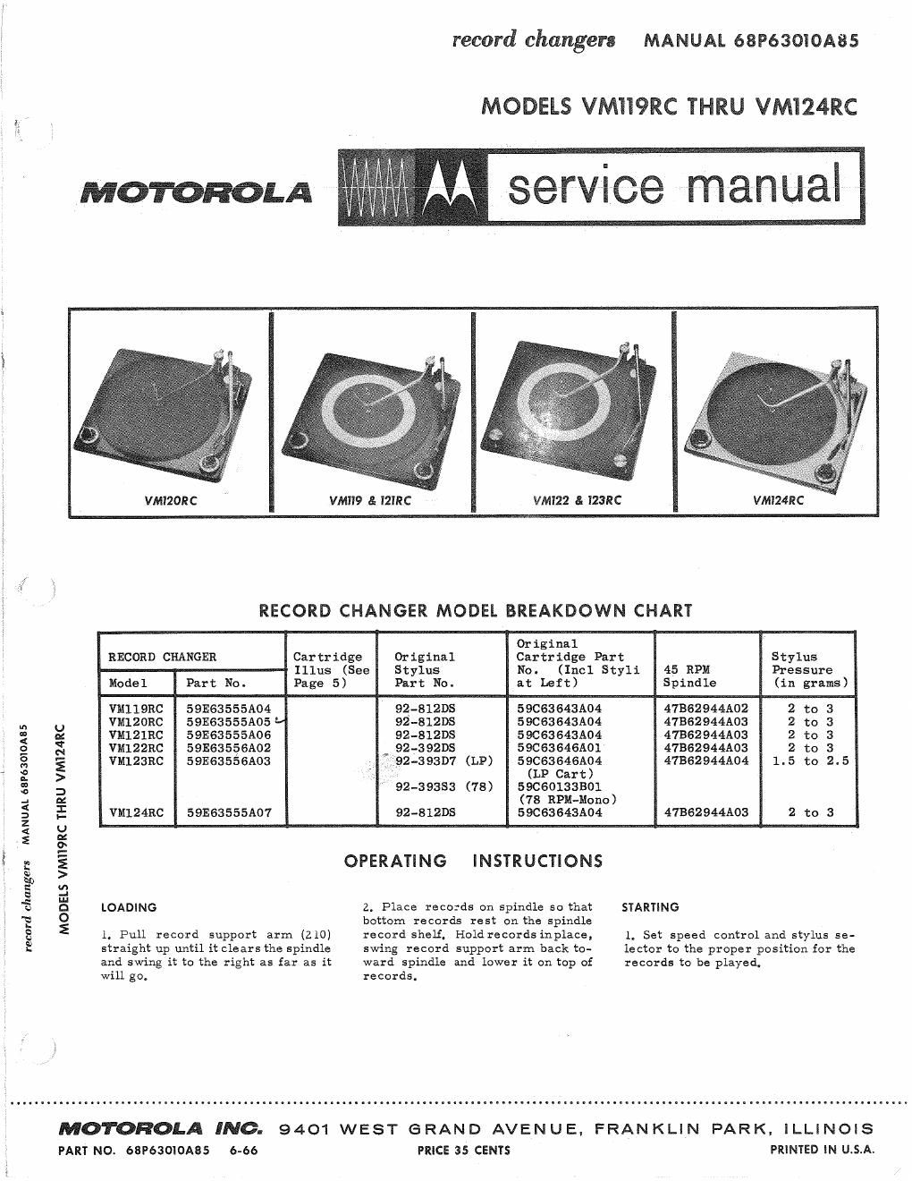
VMT2ORC VMII9 & IZIRC VM122 8: I23RC VMI24RC
If
RECORD CHANGER MODEL BREAKDOWN CHART
Original
RECORD CHANGER Cartridge Original Cartridge Part Stylus
Illus (See Stylus No. (Incl Styli 45 RPM Pressure
Model Part No. Page 5) Part No. at Left) Spindle (in grams)
VMIIQRC 59E63555A04 92-812DS 59063643A04 47362944A02 2 to 3
m U VMIZORC 5913635551105 92-81205 59C63643A04 47BS2944A03 2 to 3
3 a: VMlZlRC 59E63555A06 92-812113 59C63643A04 4786294415103 2 to 3
g g VM122RC 59E635§6A02 . 92-392DS 59C63646A01 47862944A03 2 to 3
g g VM123RC 59E63556A03 1-92-393D7 (LP) 59C63646A04 47B62944A04 1.5 to 2.5
2 > ,' (LP Cart)
3 3 92-39383 (78) 59060133801
2 x (78 RPM-Mono)
; E VM124RC 59E63555A07 92-812DS 59063643A04 47B62944A03 2 to 3
5 a
2 2
I § E OPERATING INSTRUCTIONS
N
32° u:
a d
\ '5 :1 LOADING 2. Place records on spindle so that STARTING
"a 0 bottom records rest on the spindle
g E 1. Pull record support arm (210) record shelf. Holdrecords inplace, 1. Set speed control and stylus se-

will go.

MOTOROLA INC.
PART No. 68P63OIOA85 6-66

straight up until it clears the spindle
and swing it to the right as far as it

swing record support arm back to-
ward spindle and lower it on top of

records.

PRICE 35 CENTS

letter to the proper position for the
records to be played.

9401 WEST GRAND AVENUE. FRANKLIN PARK. ILLINOIS

PRINTED IN U.S.A.

Page 2

2.. Turn OFF-ON-REJ knob (or
lever to "REJ" and release. The
changer will automatically play and
change each record, shutting itself
off after the last record has been
played.

REJECYING

To reject a record at anytime while
the changer is operating, turnOFF-
ON-REJ knob (or lever) to HREJ
and release,

MANUAL OPERATION

To play records manually, lift the
record support arm clear of the
center spindle and swing it to the
right as far as itwillgo. Turn OFF-
ON-REJ knob to HREJ" andrelease.
The changer will cycle and the tone
arm will set down on the rest post
while the turntable continues to turn,
The changer is now readyfor manual
operation. Select proper speed and
stylus. Place a single recordonthe
turntable and set the tone armgently
on the record. When the recordhas
been played, the changer will cycle
automatically, returning the tone
arm to the rest post, The record
can then be removed and another one
placed on the turntable.

CHANGE CYCLE

This record changer uses avelocity
trip mechanism which is actuatedby
the faster inward motion of the tone
arm when the needle enters the trip
grooves at the end of the record,
Only records having fast finishing
grooves will operate this trip mech-
anism.

To better observe the sequence of
the change cycle, place the record
changer on a dolly and position it so
that you are looking at the back of
the changer. Tilt the back of the
changer up slightly so that you can
see the cycling mechanism.

Watch the trip link (443), rotate the
off-on-reject knob to the "reject
position. Note thatthe trip link (443)
moves back engaging the trip lever
(448). The rotating motion of the trip
lever (448) activates the trip lever
clutch (450), moving the trip pawl
toward the turntable hub. Contact
between the trip pawl and the pro-
jection on the turntable hub starts
the gear assembly (441) into motion.
The teeth on the gear assembly (441)
mesh with the teeth on the turntable
hub to drive the gear through cycle.

The rotation of the gear (441) starts
the lateral travel of the slide assem-
bly (445). An eccentric mountedpin
on the gear assembly (441) moves the
slide assembly (445)towardthe rear

2

of the changer.

As the slide assembly (445) begins
to move the inclined surface on the
rear of the slide raises the lift pin
(435) which in turn raises-the tone
arm. When the lift pin reaches the
top of the incline, the large tab on
the back of the slide rotates the
finger and shaft assembly, moving
the tone arm away from the center
spindle.

The slide continues to move back
bringing the tab on the rear of the
slide in Contact with the short tail on
the locator plate (426), Atthis time,
the pressure exerted by the lift pin
spring causes the formeddimples in
the trip finger and shaft assemblyto
engage the holes inthe locator (426).

After the tone arm is out ofthe way,
another tab on the slide assembly
actuates the ejector bracket assem-
bly (428).

The ejector bracket assembly (428)
moves the push rod (417) upward.
This moves the recordpusher,inthe
center spindle, to drop the next
record.

As the gear assembly (441) continues
to turn, the formed tab on the top of
the gear contacts the reset lever
(419) moving it to the 10 position,
At the same time, the slide continues
to the end of its travel to the rear
and starts forward,

If a 7" record is dropped, the 7'I
lever (422) is free to move upward,
This lifts the reset lever (419)to the
7" set down position.

If a 10H record is dropped, the 7
lever (422) cannot move upward be-
cause the bumper (424) on the 7"
lever hits the edge ofthe 10 record,
Consequently, the reset lever (419)
will remain in the 10U position.

If a 12" record is dropped, the edge
of the record strikes the 12 selec-
tor (402). This releases the reset
lever (419) and allows it to drop into
the 12" set down position.

As the slide assembly (445) moves
forward, the tab on the rear of the
slide slowly releases the locator
(426) and the finger and shaft assem-
bly (436) which are still meshed to-
gether, The return spring (421)
causes the tone arm to move inward
toward the center spindle. As the
locator (426) and the finger and shaft
assembly (43 6) move inward,the re-
set lever stops the locator at the
proper position for the size record
being played.

As the slide (445) continues forward,
the lift pin spring releases the pres-
sure on the finger and shaft as sembly
(436) releasing it from the locator
(426). A tab on the gear (441) rides

along the curved surface of the re-
tard assembly placing aslightpres-
sure on the retard lever (437). This
holds the tone arm near the starting
grooves of the recorduntil the needle
catches in the groove.

Just before the slide assembly(445)
and gear assembly (441) reach the
end of the cycle, a tab near the front
of the slide contacts the trip lever
and moves it into position ready to
be tripped again.

After the record has played, the trip
finger of the finger and shaft assem-
bly (436) moves the trip link (443)
to start the cycle over again,

When the last record is dropped to
the turntable, the record support
(210) drops down causing the record
support shaft (249) to Contact the stop
arm on the record support guide
assembly (245). The stop arm in
turn applies pressure to the shutoff
lever (431). At this moment, the
slide assembly (445) is in its outer
most position, away from the
spindle, and the shut off lever (431)
is forced against the escape lever,
preventing the shut off lever from
lowering further, As the slide con-
tinues forward, the end of the shut
off lever (431) slides off the escape
lever and drops down through the slot
in the slide. By this time, the loca-
tor (426) has rotated too far to be
blocked by the shut off lever andthe
tone arm is permitted to set downon
the record.

After the last record has finished
playing, the changer trips and goes
into cycle, After this slide assembly
(445) has reached its outermost po-
sition, the force applied to the shut
off layer (431) by the record support
shaft (249) causes the endofthe shut
off lever (431) to raise up and pre-
vent the locator from rotating. This
positions the tone arm directly over
the rest post.

As the slide assembly moves back
toward the spindle, the stop arm on
the record support guide assembly
holds the trip link (443) up so that
the tab on the end of the trip link hits
the control lever (410), As the slide
moves further along, the trip lever
(448) on the gear pushes a tab onthe
end of the trip link (443) pulling it
towards the center. This turns the
AC switch (250) to the off position.

In manual play, when the record sup-
port is raised and rotated to the
extreme right, it releases the pres-
sure placed on the manualplay lever
(413) by the manual play lever spring
(412). When the changer cycles,the
manual play lever drops down far
enough to prevent rotation of the lo-
cator causing the tone arm to set
down on the rest post. When this
happens, the AC switch is not actu-
ated, thus, the motor remains on.