Motorola ts 919 schematic

This is the 2 pages manual for motorola ts 919 schematic.
Read or download the pdf for free. If you want to contribute, please mail your pdfs to info@audioservicemanuals.com.

Page: 1 / 2
left right
motorola ts 919 schematic

Extracted text from motorola ts 919 schematic (Ocr-read)


Page 1

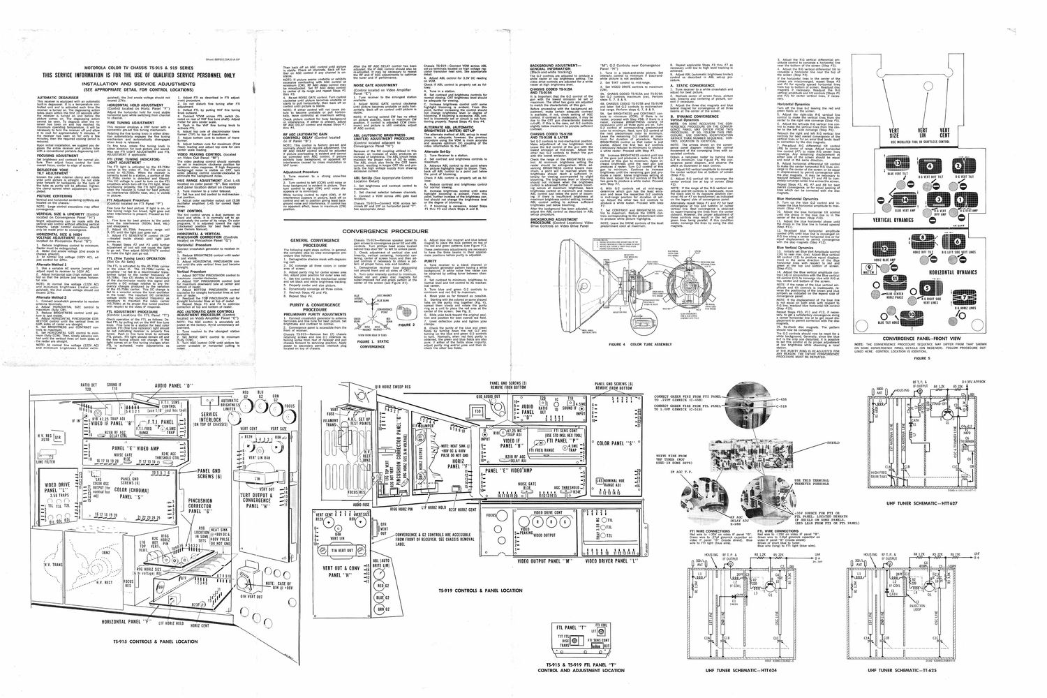
MOTOROLA COLOR TV CHASSIS TS-915 & 919 SERIES 4

Sheet 68P65129A39-A-UF

THIS SERVICE INFORMATION IS FOR THE USE OF OUALIFIED SERVICE PERSONNEL ONLY

INSTALLATION AND SERVICE ADJUSTMENTS
(SEE APPROPRIATE DETAIL FOR CONTROL LOCATIONS)

AUTOMATIC DEGAUSSER

This receiver is equipped with an automatic
built~in degausser. It is a temperature con-
trolled unit and is activated each time the
receiver is turned on. The degaussing action
takes place within the first 10 seconds after
the receiver is turned on and before the
picture comes on. The degaussing action
cannot be seen. To degauss after the re-
ceiver has been on and has reached its
maximum operating temperature, it willsbe
necessary to turn the receiver off rid allow
it to cool for approximately' 5 in notes. If
the receiver has been on for only a few
minutes, then the required cooling period is
reduced.

Upon initial installation, we suggest you de-
guass the entire receiver and picture tube
with a conventional portable degaussing coil.

FOCUSING ADJUSTMENT

Set brightness and contrast for normal pic» '

ture. Then adjust focus control for best
overall focus, center to edge of screen.

DEFLECTION YOKE

TILTr ADJUSTMENT "

Loosen the yoke retainer clamp and rotate
yoke until picture is straight. Do not slide
yoke forward or backwards on the neck of
the tube as purity will be affected, Tighten
ETIIE! izcllamp screws when adjustment is com-

. pee . ,

PICTURE CENTERING

Vertical and horizontal centering? mines... «,-»

located on the chassis:

NOTE: Large cbntrol excursions may affect
convergence.

.VERTICAL SIZE & LINEARITY (Control
located on, Convergence Panel H")
Slight adjustments can be made with the
vertical size control without affecting vertical
linearity. Large control excursions should
only be made prior to convergence.

HORIZONTAL SIZE & HIGH
VOLTAGE ADJUSTMENT (Control
located on Pincushion Panel G")

1. Reduce brightness control to minimum.
Raster must be extinguished.

2. Meter 2nd anode voltage (2nd anode to
chassis ground).

3. At normal line voltage (122V AC), ad-
just control for 27Kv. . .

Alternate Method 1

1. Use a variable AC source (variac) and
adjust input to receiver to 102V AC. .
2. Adjust horizontal size (high voltage) con
trol so that the picture just makes horizon-
tal size.

NOTE: At normal line voltage (122V AC)
and minimum brightness (raster extin-
guished), the 2nd anode voltage should not
exceed 27_Kv.

Alternate Method 2

1. Connect crosshatch generator to receiver
antenna terminals,

2. Adjust lHORIZDNTAL SIZE control to
maximum (fully CW). '

3. Reduce ERIGHTNESS controluntil pic»
ture is just visible. .

4. Adjust HORIZONTAL PINCUSHION COR-
RECTOR control until the vertical lines on
both sides of raster are .straight.

5. Set BRIGHTNESS and CONTRAST con-
trols to maximum.

6. Set HORIZONTAL SIZE Control to mini-
mum (fully CCW). Then, slowly advance con
trol until the vertical lines On both sides of
Ithe ras'ter are straight. .'
NOTE: 'At normal line voltage '(122V AC)
and minimum brightness (raster extin-

guished), the 2nd anode voltage should not
exceed 27Kv.

HORIZONTAL HOLD ADJUSTMENT

(Control located on Horiz. Panel "F")-

Adjust the horizontal hold for most stable
horizontal syn'c while switching from channel
to channel. -

FINE TUNING ADJUSTMENT

This receiver employs a VHF tuner with a
_ concentric pre-set fine tuning mechanism.

Rotating the fine tuning knob in either direc-
tion automatically engages the fine tuning
mechanism and automatically disengages
when knob is released.

T_o fine tune, rotate fine tuning knob in
either direction for best picture and sound.
Also see FTI LIGHT ADJUSTMENT and FTL
ADJUSTMENT if applicable.

FI'I (FINE TUNING INDICATOR)
.LIGHT ADJUSTMENT ~

The FTI light is activated by the 45.75Mc
carrier in the video IF. The FTI circuit is
tuned to 45.75Mc. When the receiver is
correctly tuned to a station, a portion of the
45, 75Mc carrier is detected and filtered.
This DC voltage is used to turn on the FTI
amphiers which turn off the PH light. When
functioning properly. the FTI light goes out
when the receiver. is tuned for best picture;

, in picture. , .

(FTI, Adjustment Procedure _

"(Control located on FTI Panel P")

Fine tune for best picture. If light is on, or
fine tuning range too broad. light goes out
when interference ls present. Proceed as fol-
lows: l

1. Fine tune for best picture to' the point
when the interference (920Kc beat, etc.)
just disappears. . .

2. Adjust 45.75Mc frequency range coil
(L-lP) until the light just goes out .

3. Adjust FI'I SENSITIVITYIcontrol (R»12P
-lo0ated inside shield) until
comes on. ,,

4. Repeat Steps #2 and #3 until further
adjustment of coil will not cause the light
to go out. Then adjust SENSITIVITY control
to make the light just go out.

FI'L (Fine Tuning Lock) OPERATION
(Not On All Sets) -

The FTL is activated by the _45.75Mc'carrier
in the video IE. .The 45.75Mc'lcarriér is
amplified :ZI'IO fed to a discriminator trans-
former tuned to the center'frequency of
45.75Mc. TWO (2) diodes iiI' the secondary
of the discriminator rectify this signal and
provide a DC voltage relative to any fre-
qLIency changes produced by the variation
of the 45.75Mc carrier. This .00 change is
fed to a varactor across the local oscillator
in the tuner. The resultant DC correction
voltage shifts the; oscillator frequency as
necessary to maintain the video carrier
(45.75Mc) at its proper fine tuned position
with respect to the video IF response.

FTL ADJUSTMENT PROCEDURE
(Control Locations 0n FTL Panel T)

Check operation of the FTL as follows: De~
feat FTL by pulling out on the VHF finetune
knob. Fine tune to a station forbest color
picture. FTI (fine tune indicator) light should
be out indicating receiVer is properly fine
tuned. Push sin fine tune ,knob to activate
FTL circuit. FTI light should remain off and
the fine tuning should not change. If the
light comes on or fine tuning changes when
FT.L is activated, make adjustments . as
follows: .

notinterference.(920KcAbeat, etc,) is visible,

light just.

NOTE: The A60 control Is accurately ad-
justed at the factory. Agoid unnecessary ad-I

. available.

1. Adjust FTI as described in FTI adjust-

ment procedure.

2. Do not disturb fine tuning after Fl'l
adjustment. .

3. Defeat FTL by pulling VHF fine tuning

knob outward.

4. Connect VTVM across FI'L switch (lo-

cated on rear of VHF fine tune shaft). Adjust

meter for zero center scale.

5. Push in the VHF fine tuning knob to

activate FTL.

6. Adjust top core of discriminator trans-

former (TIP) to top of transformer.

7. Adjust bottom core to bottom of trans-

former. _
8. Adjust bottom core for maximum (First 1
Peak) reading and adjust top core for zero

center scale. reading.

VIDEO PEAKING CONTROL (located
on Video Out Panel "M")

The video peaking control should normally
be set in maximum clockwise position for
optimum video response. If high frequency
backgroiuid noise is visible on CRT, turn
video peaking control counter-clockwise .to
eliminate the background noise.

HUE RANGE ADJUSTMENT (Coil, L-4S
located on color panel S". See control
and panel location detail on chassis)

1. Tune receiver to 9 color telecast.

' 2. 'Set- hue-and tint control to mid-mechani -,

ical position,

3. - Adjust color oscillator output coil (3.58
oscillator amplifier) L-AS for correct flesh
tones. ,

TINT CONTROL .

The tint control serves a dual purpose; on
black and white. it is normally set to ap-
proximately the center of its range. On color
programs, it is adjusted toward the right
(clockwise) position for best flesh tones
(see Owners Manual).

HORIZONTAL Bi VERTICAL
PINCUSHION CORRECTION (Controls 3
located on Pincushion Panel "G") '. I

Horizontal Procedure

Connect crosshatch generator to receiver in-
put. ,
1. Reduce BRIGHTNESS control iintll raster
is just visible. y

2. Adjust HORIZONTAL PINCUSHION con-

: trol until the side vertical lines just become

straight.
Vertical Procedure

, 1. Adjust BOTTOM PINCUSHION control to

maximum counter-clockwise.

2.;Adjust TOP PINCUSHION control (coil
for maximum downward bow at center and
bottom of raster. '

3. Adjust BOTTOM PINCUSHION control
clockwise for straight horizontal lines at bot-
tom of raster. . "

4. Readjust the TOE PlNCUSHION coil for
straight horizontal lines at top of raster.

5, Repeat Steps #3 and #4 to optimize
correction at top and bottom of raster.

AGC (AUTOMATIC aAiN CONTROL) 2

ADJUSTMENT PROCEDURE (Control _
located on Video-Amplifier Panel "E")

justment. . ..
1. Tune receiver tothe' strongest station

imum

2. set NOISE GATE control to "1'
(fully CCW). ; i U 3
3. Turn AGC control CCW until picture he»
comzs unstable or horizontal pulling is
note ., ' ' .

Then back off on AGC control until picture
is stable. Check all channels. Back off fur-
ther on AGC control if any channel is unv
stable. . ,
NOTE: If picture seems unstable or exhibits
excessive overloading with AGC control at
minimum (CW), RF AGC delay control may
be misadjusted. Set RF AGC delay control
to center of its range and repeat Steps #1
thru #3,

4. Re-set NOISE GATE control. Turn control
clockwise until picture becomes unstable or
starts to pull horizontally, then back off on
control until picture is stable.

NOTE: If either control will not cause pic-
ture to become unstable orIpull horizon-
tally, leave control(s) at maximum setting.
Check picture content for busy background
or interference. If either is present, adjust
RF AGC DELAY control and repeat Steps #1
thru #4.

RF AGC (AUTOMATIC GAIN

CONTROL) DELAY (Control located

on IF Panel 8")

NOTE: This control is factory pre-set and
normally should not require adjustment. The
RF AGC DELAY control should be adjusted
if picture overloading is evident and cannot
be corrected with AGC control. if picture
exhibits busy background, or apparent RF
interference caused by cross modulation in
VHF tuner.

Adjustment Procedure

1. Tune receiver to a strong snow-free
station.

2. Turn control to left (CCW) until noise or
busy background is evident in picture. Then
turn control to right (CW) until noise dis-
appears or is minimized.

While turning control to right (CW), if RF
interference appears in picture. back off on
control and set to position giving least back-
ground nolse and interference. If control has
no apparent effect, leave in maximum (CW)
position.

After the RF AGC DELAY control has been
adjusted, the IF AGC control should also be
re-adiusted. It may be necessary to repeat
the RF and IF AGC adjustments to optimize
the tuner and IF performance.

NOISE GATE ADJUSTMENT

(Control located on Video Amplifier
Panel "E")

1, Tune receiver to the strongest station
available.

2. Adjust NOISE GATE control clockwise
until picture becomes unstable or pulls hori-
zontally. Back off on control until picture is
stable.

NOTE: If turning control CW has no effect
on picture stability, leave in maximum CW
position. If control is adjusted CCW (mini-
mum) and picture is still unstable, adjust
IF AGC control.

ABL (AUTOMATIC BRIGHTNESS
LIMITER) ADJUSTMENT PROCEDURE

(Control located adjacent to
Convergence Panel "H)

Because of the DC coupling utilized in this
receiver. an increase of video produces an
increase of brightness. The ABL circuit helps
maintain the proper ratio of DC to video.
The ABL circuit also limits the CRT beam
current. resulting in longer CRT life and pro-
tects the high voltage supply from drawing
excessive current,

ABL Set-Up (See Appropriate Control
Location Detail)

1, Set brightness and contrast control to
maximum.

2. Set channel selector between channels.
3. Connect a VOM across ARC gate load
resistors.

Chassis TS-915-Connect VOM across ter-
minals 8F and 10F on horizontal panel F".
See appropriate detail.

Chassis TS-919-Connect VOM across ABL
set-up terminals located on high voltage reg-
ulator transistor heat sink. See appropriate
detail.

4. Adjust ABL control for 3.3V DC reading
on VOM.

Check if ABL control is properly set as fol-
lows:

A. Time in a station.

B. Set contrast and brightness controls for
normal viewing. CRT brightness level should
be adequate for viewing.

C. increase brightness control until some
highlight blooming is evident. From this
point, further increasing the control should
not change brightness level or degree of
blooming. If blooming is excessive, ABL con-
trol is incorrectly set or circuit is not func-
tioning properly. Repeat Steps #1 thru #4.

ALTERNATE ABL (AUTOMATIC
BRIGHTNESS LIMITER) SET-UP

The alternate method of ABL set-up in most
cases is adequate; however, the previous
procedure using the VOM is more accurate
and assures optimum DC coupling of the
video information to the CRT.

Alternate Set-Up

1. Tune Receiver to a station.

2. Set contrast and brightness controls to
maximum.

3. Advance ABL control to the point where
the picture highlights begin to bloom. Then,
back off ABL control to a point just below
the point of blooming.

Check if ABL control is properly set as fol-
lows:

A. Reduce contrast and brightness control
for normal viewing.

B. Increase brightness control until some
highlight blooming ls evident. From this
point, further increase of the brightness con-
trol should not change the brightness level
or the degree of blooming.

C. If blooming ls excessive, repeat Steps
#1 thru #3 and check Steps A and E.

CONVERGENCE PROCEDURE

GENERAL CONVERGENCE
PROCEDURE

The following eight steps outline, in general,
the complete step by step convergence pro
cedure that follows:

1. Demagnetize shadow mask with degauss-
ing coil.

2. DC converge all three colors in center
area of screen.

3. Adjust purity ring for center screen area
red, adjust yoke position for outer area red.
4. Set tint control to its mechanical center
and set black and white brightness tracking.
Properly center and size picture.
Dynamically converge all three colors.
Recheck Steps #2 and #3.

Repeat Step #4.

snow

PURITY & CONVERGENCE
PROCEDURE
PRELIMINARY PURITY ADJUSTMENTS
1. Connect crosshatch generator to antenna
terminals and fine tune for best picture. Set

brightness and contrast to normal.

2. Convergence panel is accessible from the
front of receiver.

Chassis TS-915-Remove two (2) chassis
retaining screws and one (1) interlock re-
taining screw from rear of receiver and pull
chassis forward to servicing position. Apply
power to secondary service interlock plug
located on top of chassis.

Chassis TS-919-Remove speaker panel to
gain access to convergence panel GE and ABL
controls. Turn phillips head screw located
behind trap door 90 to left to unlock panel.
3. Check adjustment of vertical size and
linearity, vertical centering, horizontal cen-
tering, center of screen focus and then ad-
just controls if necessary to obtain a pat-
tern of proper focus, size and location.

4. Demagnetize receiver (use degaussing
coil around front and all sides of CRT).

5. Turn color intensity control to minimum.
Adjust red and green disc magnets for
super-imposed red and green pattern at the
center of the screen (see Figure #1).

DISC MAGNET

/ BLUE BEAM
<=é>

BLUE
LATERAL
MAGNET

CONVERGENCE

POINT
GREEN .. R RED

EEAM BEAM

% DECK
MAGNET MAGNET»

DISC FIGURE 2

(VIEW FROM REAR OF TUBE)

FIGU RE 1. STATIC
CONVERGENCE

6. Adjust blue disc magnet and blue lateral
magnet to place the blue pattern on top of
the red and green patterns (see Figure #1).
These preliminary adjustments are necessary
to have the three beams in their approxiA
mate positions before purity is adjusted.

PURITY

1. Tune receiver to a blank channel or
crosshatch generator pattern having a white
background. A white noise free raster can
be obtained by setting tuner between chan-
nels.

2. Set contrast to minimum, brightness to
normal level and tint control to its mechan-
ical center.

3. Turn blue and green G-2 controls to
minimum and red (3-2 to maximum.

4. Move yoke as far forward as possible.
5. Starting with the colored or same shaped
tabs on the purity ring together (Fig. 4),
spread them slowly and rotate the purity
ring as a unit to place the red area at the
center of the screen. See Fig. 2.

6. Slide yoke back toward the original posi-
tion and position for best overall red field,
7, Level deflection yoke and tighten yoke
clamps.

8. Check the purity of the blue and green
fields by turning down the red 62 and
turning up the blue and green G~2 controls
in turn. Normally, when red field purity is
obtained, the green and blue fields are also
pure. If either of the fields show impurity,
adjust purity ring and/or yoke and then re-
check the other two fields.

BACKGROUND ADJUSTMENT-
GENERAL INFORMATION
(Black-andwhite tracking)

The 6-2 controls are adjusted to produce a
white raster at low brightness setting. The
video drive controls are adjusted for a white
raster at high brightness level,

CHASSIS CODED TS-915A

AND TS-919A

It is important that the 6-2 control of the
gun with the lowest emission be set at
maximum. The other two guns are adjusted
to match the characteristic of this gun.
Before proceeding with the background ad-
justment, make certain adequate contrast
is available. If not. check setting of A60
control. If contrast is inadequate, it may be
due to the CRT gun characteristic (remote
cut-off). if this is the case, set G-2 controls
slightly below maximum to provide sufficient
contrast.

CHASSIS CODED TS-9153

AND TS-919I3 & LATER

Set G-2 controls to midvmechanical position.
Make adjustment at low brightness level.
Leave the (32 control of the gun with the
lowest emission at mid-range. Adjust the
other two G2 controls to match the gun
with the lowest emission,

Check the range of the BRIGHTNESS con-
trol. At minimum brightness setting the
raster should be extinguished. While ad-
vancing BRIGHTNESS control toward max-
imum, a point will be reached where the
brightness should reach a sufficient in-
tensity for viewing accompanied by slight
blooming. The brightness level or blooming
should not increase when the brightness
control ls advanced further. If severe bloom»
ing occurs at maximum brightness, leave
brightness control at maximum and reduce
ABL control Just below the point of bloom-
ing. If there is insufficient brightness at
maximum brightness control setting, increase
ABL control setting to achieve sufficient
brightness just below blooming.

After the background has been adjusted, re~
adjust the ABL control as described in ABL
set-up procedure.

BACKGROUND ADJUSTMENT
PROCEDURE (Control Locations: Video
Drive Controls on Video Drive Panel

M"; G-2 Controls near Convergence
Panel "H)

1. Tune in a black-and-white picture, Set
intensity control to minimum if black-and-
white picture is not available.

2. Set TINT control to mid-range.

3. Set VIDEO DRIVE controls to maximum
(CW).

4A. CHASIS CODED TS-915A and TS-919A:
Set G-2 controls maximum (cw). Perform
steps 5, 7, 8 5: 9.

4B. CHASSIS CODED TS-QISB and TS-QIQB
and later: Set 62 controls to mid-mechan»
ical range. Perform steps 6, 7, 8 81 9.

5A. Set BRIGHTNESS and CONTRAST con-
trols to minimum (CCW). If there is no
raster, proceed with Step #53. If there is a
raster, increase BRIGHTNESS control (if
necessary) until all three guns are on. Turn
62 control of corresponding predominant
color to minimum. Next, turn G-2 control of
the next predominant color to minimum.
Leave the remaining G-2 control at maxi-
mum for duration of procedure. Reduce
BRIGHTNESS control so that raster is just
visible. Adjust the first two 6-2 controls
(previously reduced to minimum) to produce
a white raster. Proceed with Step #7.

SB. Increase BRIGHTNESS control until one
of the guns just produces a raster. Turn G-2
control of this gun to minimum. Again in-
crease brightness until the next gun just
produces a raster. Turn G-2 control of this
gun to minimum. Continue to increase
brightness until the remaining gun just pro-
duces a raster. Leave brightness setting at
this level. Adjust the G-2 controls of the first
two guns to produce a white raster. Proceed
with Step #7.

6, With (3-2 controls set at mid»range.
determine which gun has the least emis-
sion and leave the respective (32 controls
in mid-range position for duration of set-
up. Adjust the other two G-2 controls to
pgroduce a white raster. Proceed with Step
7.
7. Set CONTRAST and BRIGHTNESS con-
trol to maximum. Reduce the DRIVE con-
trols corresponding to the predominant color
to produce white picture highlights.

NOTE: Leave the DRIVE controls of the least
predominant color at maximum.

nnMIIIINc cm.

I. INSIALL DEHECVIDN YuKE AGAIMSI am or LItl

2. INSTALL CDNVTDGENCE voxr AS shown In msiRi

I. iNsi/ILL IILUL mom It will" llth ASSIM
MAINS! CONVERGENCE voxr


\MEIAL SHIELD

mm on Au. snsl

bEFLtETlO N
VOKE RETAIN INC
SCREWS
iiiut tAiLRAL

CONVERGENCE van»
POSITION AS
SHOWN IN Insrin

urrchriuN YOKE


FIGURE 4

8. Repeat applicable Steps #3 thru #7 as
necessary until low to high level tracking is
achieved.

9. Adjust ABL (automatic brightness limiter)
control as described in ABL setup pro-
cedure,

A. STATIC CONVERGENCE

1. Tune receiver to a white crosshatch and
adjust for best picture.

2. Recheck center of screen focus, picture
size, linearity and centering of picture, cor»
rect if necessary.

3, Adjust the three disc magnets and blue
lateral magnet for convergence of all three
beams at the center of the screen.

B. DYNAMIC CONVERGENCE

Vertical Dynamics

NOTE: ON SOME RECEIVERS THE CON-
VERGENCE PROCEDURE ON THE CONVER-
GENCE PANEL MAY DIFFER FROM THIS
PROCEDURE. IF SO, FOLLOW THIS PRO-
CEDURE. USE CONTROL IDENTIFICATION
RATHER THAN NUMBER SEQUENCE. CON-
TROL LOCATION IS IDENTICAL.

NOTE: The arrows shown on the conver-
gence panel diagram indicate the normal
movement of the converging lines with as-
sociated controls.

Obtain a red-green raster by turning blue
(32 to minimum. Use Figure #5, the con»
vergence panel diagram, and observe the
affect as illustrated at each control.

1. Adjust R-G vertical amplitude to converge
the center vertical line at bottom of screen
(Step #1).

2. Adjust R-G vertical tilt to converge the
ctezgter vertical line at top of screen (Step
NOTE: If the range of the R-G vertical am
plitude and tilt controls is inadequate, move
the black wire to its opposite position (ter-
minal #6 or #7 on transformer) as indicated
on the legend side of convergence panel.
Alternately repeat Steps #1 and #2 for best
convergence at top and bottom of center
vertical line. Best convergence is obtained
by super-imposing the lines from the center
outward. However, the proper adjustment of
these controls may result in the red and
green lines being parallel. if this condition
exists, converge the lines by using the disc
magnets.

STATIC cITNv

IIIIIE mm l
l
D I SE MAGNET l

REIT liltnlAl.
I. sun: conv
. Pm IZ nisc MAGNET
ALIEN CUNVERGEMEE
um i. IILIIE LATER/ll
Assgmnvwnx I-IN I2

COLOR TUBE ASSEMBLY

3. Adjust the R-G vertical differential am-
plitude control to converge a horizontal line
near the bottom of the screen (Step #3).
4. Adjust the R-G vertical differential tilt to
converge a horizontal line near the top of
the screen (Step #4).

If the horizontal lines in the center of the
screen are misconverged, repeat Steps #3
and #4 for equally spaced horizontal lines
from top to bottom of screen. Readjust disc
magnets if necessary. Readjust the RE
vertical amplitude and tilt controls (Steps #1
and #2) for center vertical lines, if neces-
sary. '

Horizontal Dynamics

Turn off the blue G-2 leaving the red and
green fields on the screen,

5. Adjust the right-side R-G vertical line
control to make the vertical lines from the
center to the right side converge (Step #5).
6. Adjust the left-side R-G vertical line con-
trol to make the vertical lines from the cen-
ter to the left side converge (Step #6).
Retouch the right and left R-G vertical line
controls for best overall convergence of the
vertical lines or for an error that lends itself
to correction by the disc magnets.

7. Pre-adjust R-G differential tilt control
(#8) to center of range. Adjust horizontal
line control (#7) to make R~G center lines
converge. Any remaining displacement at
either side of the screen should be equal
and exist in the same direction.

3. Adjust horizontal differential tilt control
to make the center horizontal R-G lines con-
verge In the center of the screen or be equal
in displacement to permit convergence with
the disc magnets. It may be necessary to
readjust between Steps #7 and #8 to com-
pletely converge center line across the screen.
Repeat Steps #5, #6, #7 and #8 for best
overall convergence, or for equal spacing of
lines which can be corrected with the disc
magnets.

Blue Horizontal Dynamics

9. Turn up the blue G-2 control and in-
crease the blue horizontal amplitude to max-
Imum (Step #9).

10.. Adjust the blue horizontal tilt control
until the droop in the blue line is in the
center of the screen (Step #10).

11. Adjust the blue horizontal phase until
the droop in the blue line is forced upward
(Step #11).

12. Readjust blue horizontal amplitude
control (#9) until blue line is converged on
R-G line'along a center horizontal line or for
equal displacement to permit convergence
With the disc magnets (Step #12).

Blue Vertical Dynamics

13. initially set Blue Vert Amplitude control
(14) to near max. (cw). Adjust Blue vertical
tilt control (13) to produce equal displace-
ment in the same direction of the Blue
horizontal lines with respect to red and
green at the top and bottom Of screen.
(Step #13).

14. Adjust the Blue vertical amplitude con-
trol (14) in conjunction with the Blue vertical
tilt control (13) to converge blue with RC at
top, center and bottom of the screen.

NOTE: If the range of the blue vertical am
plitude and tilt controls is inadequate, re-
verse the positioning of the brown and blue
jumpers as indicated on the legend side of
convergence panel.

NOTE: if the displacement of the blue line
is not equal on both ends with respect to
R-G line, readjust blue horizontal tilt control
(step #10).

Repeat Steps #10, #11 and #12, if neces-
sary, to get a satisfactory convergence along
a center horizontal line or to get equal dis-
placement to permit correction with the disc
magnets.

15. Re-check disc magnets. The pattern
should now be converged.

The G-Z controls should now be reset for a
white background. Generally, since the blue
82 is the only one disturbed, it is possible
to set this control at its proper adjustment
at low brightness while observing a local
station.

IF THE PURITY RING IS RE-ADJUSTED FOR
ANY REASON, THE ENTIRE CONVERGENCE
PROCEDURE MUST BE REPEATED.

VERT VERT VERT
SIZE LIN CENT

LISE INSULATED TOOL ON SNAFTLESS CONTROL


BLIIE VERT AMP

VERTICAL DYNAMICS


-. nifiiiiiiiii/
HI I isms-'1
IE? 5}. Elilillliifi\

RE RE
i Eiii "ii HORIZ DIFF TILT

IIORIZ BLUE A P

HORIZONTAL DYNAMICS

LISTEN LL denser.

Ii-ii lilGllT SIDE EFL 7 IEE
inn LINES Iii-ll!!!
II-I: NOIIIZ LINES

_- /o

NOTE:

ON SOME CONVERGENCE PANEL DETAILS (ON RECEIVER).

LINED

CONVERGENCE PANEL-FRONT VIEW

THE CONVERGENCE PROCEDURE SEQUENCE MAY DIFFER FROM THAT SHOWN
_ FOLLOW PROCEDURE OUT»
HERE. CONTROL LOCATION IS IDENTICAL.


FIGURE 5
v .. .. PANEL iIIIiI SCREWS [3] RFT.P.& B+35VAPPROX
IT'ZUDDET SUJI'I'III 'F AUDIO PANEL D - \ 0111 Hum SWEEP REG REMOVE leOIlI BOTTOM IIIALYIIEOLVEAFDROSMRBEIIWTSTNM) /HOUSING IF OUTPUT R41,2K R5 22K
L IlED BLU
. Ill OUT CONNECT GREEN WIRE FROM I-TI PANEL . U. ' C5. ,.001
I W 0+0 AUTOMATIC 62 [150 Mill 10-10 IWFDI jc TLD o 0/ 5. I I I I\o TO ,271>F GIMMICK (c-45I3) /,l l x, peek.
//- . . . _ M
CONTROL I I BRIGHTNES O 9- AUDIO RA-TTO' SOUND III-5MB 5" CONNECT GREEN me FROM FTL PANEL .gSTAND OFF B C3 N.-
119376 J I 54321 [ml/3n ins, hem, LIMNER\ I 5 21W 131) ll: PANEL BET IO ® I: -25 TO 1.0m: GIMMICK (c-5113) g
43) RIB 41 ZSTTRAP iiii 15 INTENLYIECK { 7" 5-" 1'" O A "D" I I ' 51 "m 9" 3; E C
. _. , - ---_ _
'F '" :EVIDEO If PANEL "B" ()F-T-l- PANEL i~_ 8- g 23 5 ° 0 w .22 .. .. 01
_g I) mm P" 4511c .._3 [ON TOP UP CHASSIS] 1%... E F DAMPER G7 __ IO, , 0 -21 E E % ,3ng
X "9 R285 RF Lac Rim; TRAP --2 g 5 8910 IF m 41.25 Iic FTI SENS com 2' a: : N470
H.V REG 10 Q DELAYCTRL <7 ---I .1 a @ TRAP ADJ [USE STD INSLHEX TOOL] 2 s I
~ 111112 : RIZH 54321 Rlilléi a: w x, mm .. ,, E I-_-' 5 cs
XSTR h :11 J , V 5 ,1 ___,-_ , ,2 E t 6 VIDEO IF FTI PANEL P 5 o COLOR PANEL "s o sumo) g g g TRIMMER
- .. .. : l at) ,. u 2 NOTE: HEAT SINK@ - PANEL 8" 4.5MC " ._ a E
FT-l :7 PANEL E VIDEO AMP _43 T5. «5), k) I .3 g 71..., 9mm ,1; m nmnn: @111: :g 33 E 3 ml:
LEE -9 NOISE cm ME MD -2 T7 - « - c. z \ PULSE DO NOT END 9- ma RF m <2 -2 mm m mm 8
, -m m THRESHOLD CTRL_I T8 VERT LIN R4H u u . _ - ___-__._ m TUNER (m 56
LINE FILTER _l_fi_17_18_19_20 JQ 1142131415 9 1.9 I; z : HURIZ "1 o QM I o '1 USED IN some ms)
"T' r 1 g.- E g PANEL F" 0 0 cm 016
If II
I 415 L77 )1 .lLlls ,, PANEL OND U g; E ; L12 E_PANEL E VIDEO AMP -5 :123 IF AGC 12p. HIGHFREQ ,\ x _
.I14 1, SCREWS [6] 2'; u a: 7- -4 -13 TRIMIABS \--
143 L45 PANEL GND .1 a: z . l3 _3 4s NOMINAL III": 7 USE THIS TERMINAL
DRIVE "'12 CDLOR SC SCREWS [6] 3 :fl __ 14 8' NOISE GATE -2 - '1 WHENEVER possmm
VIDEO 11- OUTPUT [for 5- -|. 15 9' Riai AOCTHRESHOLD_1 "6 "5 . -
PANEL "L" :ITI nominal hue COLOR [CHROMAI . O CJE" I L 0 ill- I I l I I ® I I I I I $RZ4E 0 1T 1'21'31'41'5 0 DIAGMMUéAm-O
3.58TRAPS -14 mil] pANEL S I'ERT OUTPUT 8. - ° / K \ 0 161111119211 0 1112131415 0 I
O O F) 710-15 6-5 P'NCUSHIDN UNVEAGENCE MUSE / , UHF TUNER SCHEMATlC-HTT627
:1 III m T2L .Tg a4 », CURREBTUR PANEL "H" A IIIIHIIIZPI LIFHORIZ HOLD
2 8 3 PANEL 6" o 5 4 O N R23FHDRIZCENT o o 05 4 3 2 1 0
.I7 , 16 6,2 3 2 1 VIDEO DRIVE CONT I I I I I - +35v SOURCE FOR FTI 0R
1 181920 VERT CENTI I I I IVERTSIZE FOCUS fi- m mm. LOCATED BMW...
6 L -'-T' ' 212223 5 TL RING) R3" - O ® ®\ 2 OT EELTSCADJ IF SHIELDOON sour: PANELS.
. | (H as R-ZBB (RED LEAD FROM FTI OR FTL PANEL)
- - ..._ 13L
LULYEIVIDN NEAT SINK V- @ V VERT -* O VIDED m O O FTI WIRE CONNECTIONS FTL WIRE CONNECTIONS
IN SOME @+suvnc& a- IIiII _' 0' CONVERGENCE II 112 CONTROLS iIIE ACCESSIBLE EPEAK'NGVIUEU uunur EOTZL 39 wire. 0 +33) 5" WP, Panel 3 ged We. $3153 1 PM, 135",;
SETS 430v PULSE 9- VERT UN " FROM FRONT OF RECEIVER. SEE CHASSIS REMOVAL O a: '- viifeeé If"§ai.°.1~a"u EI'ISIIIS .2?§§§5°%132 RESALE;L's-Ipani'léEEIeéa)?° °
*9 "I" 6N 1 TTT I LABEL 2- e W ° F "g (9 Wm Slfléifi; imitlfleril itlirtm... wire)
.,_ "1 '
«7 murmur/73 1" III '1' 3
(6/ / Cl _ ° /\ ° ° 05 7 5 9 J " 123.1415; 3 HOUSING RFT.P.& R41.2l< R522K UHF HOUSING RFT.P.& R4 1.2K R522I< R615K glf
\- .. .. 5+ -
ABL All": VIDEO OUTPUT PANEL M" VIDEO DRIVER PANEL L OUTPUT 32%. OUTPUT
-15 BRITELIM
ROG IIORIZ SIZE VERT OUT 8. CONV .14 7:,
[8. hi voltage] ADJ PANEL .1 n -13 L1
-12
. ~11 , L2
NOTEUIHCEEEAV RED (:2 L 1r COIL
"TS-919 CONTROLS ii. PANEL LOCATION 631m
Q BLUE (:2
INJECTION
aIIN OZ w LOOP ..
O o E i E E E
_I .4 _.I
u n j. u j. j; o
HORIZONTAL PANEL F (1|: HORIZ HOLD HORIZ CENT H H FTI COIL fl 8 2 fi 8
FTL PANEL T In ,
U
TIT FTL
ClA CIA CIC
TS-9I5 CONTROLS & PANEL LOCATION DISC F" 59" \ \
TRANS R31 H_____,,, -_\
I)1A6\63D65136A6270 DIAG 63D65136A64-0
TS-9I5 8. Ts-919 FTL PANEL "T"

CONTROL AND ADJUSTMENT LOCATION UHF TUNER SCHEMATlC-HTT624 UHF TUNER SCHEMATIC-TT-625