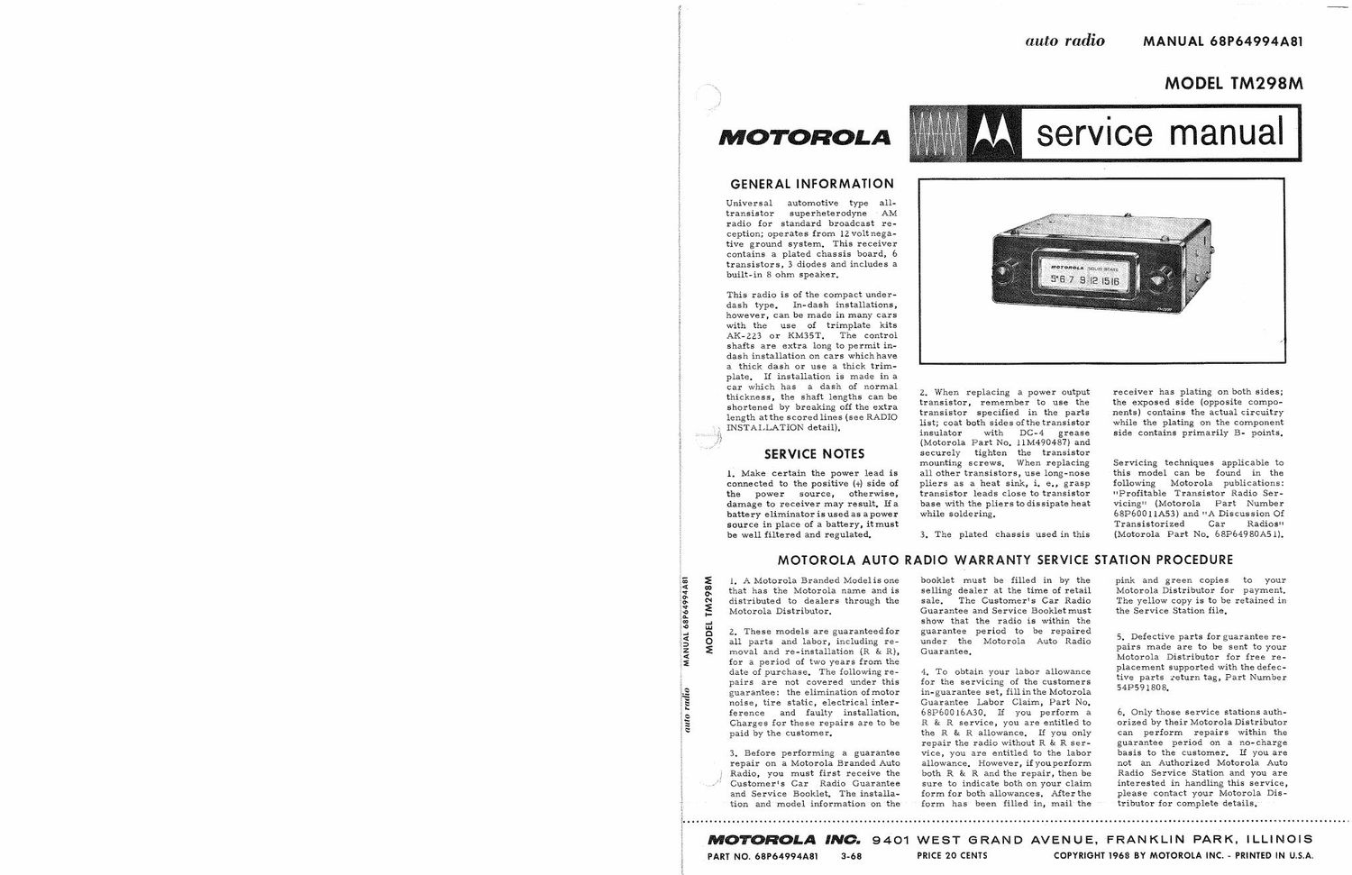
Motorola tm 298 m service manual

This is the 4 pages manual for motorola tm 298 m service manual.
Read or download the pdf for free. If you want to contribute, please mail your pdfs to info@audioservicemanuals.com.

Page: 1 / 4
left right
motorola tm 298 m service manual

Extracted text from motorola tm 298 m service manual (Ocr-read)


Page 2

ALIGNMENT

Connect an output meter across the speaker voice coil. Set volume to maximum. Attenuate signal generator
output to maintain 1 watt (2.83 volts across an 8 ohm load) on output meter at all times.

GENERATOR
GENERATOR FREQUENCY
STEP CONNECTION (400 cycle 30% mod) TUNER SET TO ADJUST REMARKS E
IF ALIGNMENT
1. To collector of 262.5Kc Hi end stop 1, 2, 3 Adjust for maximum.
RF amp thru & 4
.lmf S: chassis
RF ALIGNMENT
2, Antenna recept- 1610Kc Hi end Itop 5, 6 £1 7 Adjust for maximum.

acle thru dummy
(see Figure)

NOTE: Do not perform Steps 3, 4, 5 and 6 unless the tuner has been tampered with or associated Compo-
nents have been replaced. Remove the escutcheonto expose core screws. Before proceeding with
Step 3, back the tuning cores as far as possible out of the coils to eliminate their effect on trimmer
adjustments.

3. Antenna recept- 1610Kc Hi end stop 5, 6 8: 7 Adjust for maximum.
acle thru dummy
(see Figure)

4. " lOZOKc Tuner carriage 8, 9 8; Adjust for maximum.

' .298" from hi 10

end stop

5. " 1610Kc Hi end stop 5, 6 8: 7 Adjust for mazdmum.

6. Repeat Steps 4 and 5 untilnofurther increase; Step 5 should be last step. Then cement core screws
in place.

ANTENNA TRIMME R

7. ... ..

Weak station 7 Adjust for maximum with
around 1400Kc car radio installed in car
and antenna fully extended.

*THESE ADJUSTMENT POINTS ARE

ACCESSIBLE FROM FRONT OF RADIO plug mm RECEIVER

2
.
I


5 o I- --- -__ I ANTENNA RECEPTACLE
: *6 IO SIGNAL .-.J 5°" TO RECEIVER
3 GD GENERAmR -1 " ANTENNA
, 4 | I Reczmcu
: METAL SHIELD CAN
t ANT L__ _ __Jl MUST BE AflACflED
£ ' EC EPT m PLUG
3 DUMMY ANTENNA DETAIL
a V
f; - ALIGNMENT
LOCATION
; DETAIL
4 HEX
ALIGNMENT
_, TOOL
9 / \
TOP BOT \\
3 V
3 TOP
é: DIAL SCALE BACKGROUND 00R: .
\ l- POINTER CALIBRATION MARK
.* H m a
_ e-------_....-__-.._-__..-_--_-_ TURNS
»---,r\--------- .., 59:34
/ 1 TURN
KNOT & CEMENT

POINTER. - WITH TUNER SET TO .
1610 KC, SET POINTER T0 MARK SET-TUNER SO CORES ARE
SHOWN AND CEMENT TO DIAL STRING. OUT 0F.COILS I161!) KC) SHAFT

i DIAL STRINGING DETAIL IF ALIGNMENT DETAIL