Motorola tm 297 m service manual

This is the 4 pages manual for motorola tm 297 m service manual.
Read or download the pdf for free. If you want to contribute, please mail your pdfs to info@audioservicemanuals.com.

Page: 1 / 4
left right
motorola tm 297 m service manual

Extracted text from motorola tm 297 m service manual (Ocr-read)


Page 1

s
?

MANUAL 68Pb4994A7I

auto radio

MODEL TM297M

MOTOROLA

GENERAL INFORMATION

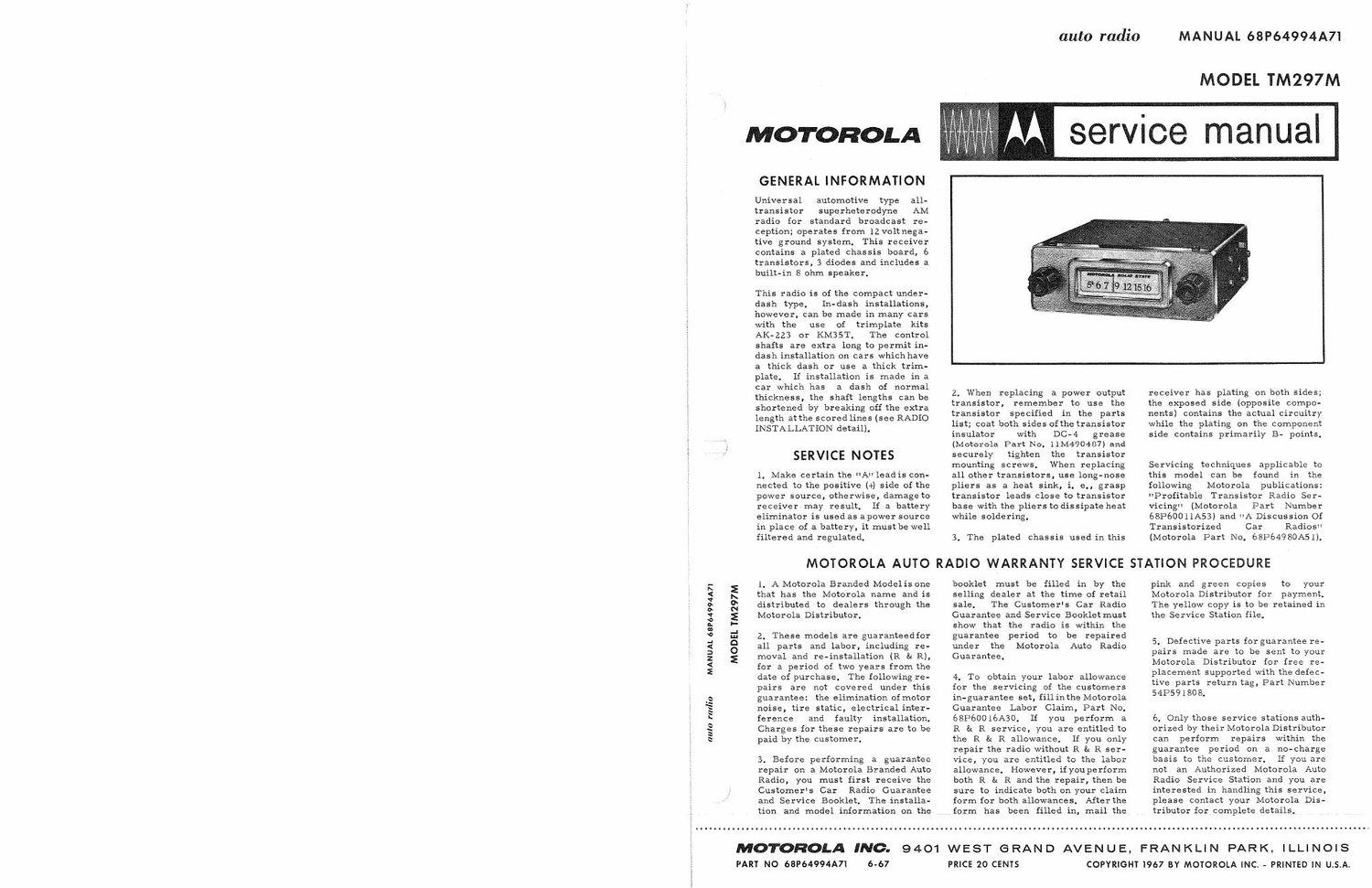
Universal automotive type all-
transistor superheterodyne AM
radio for standard broadcast re-
ception; operates from 12 voltnega-
tive ground system. This receiver
contains a plated chassis board, 6
transistors, 3 diodes and includes a
built-in 8 ohm speaker.

This radio is of the compact under-
dash type. In-dash installations,
however. can be made in many cars
with the use of trimplate kits
AK-zz3 or KM3ST. The control
shafts are extra long to permit in-
dash installation on cars which have
a thick dash or use a thick trim-
plate. If installation is made in a
car which has a dash of normal
thickness, the shaft lengths can be
shortened by breaking off the extra
length atthe scored lines (see RADIO
INSTALLATION detail).

SERVICE NOTES

1. Make certain the UA lead is con-
nected to the positive (+) side of the
power source, otherwise, damage to
receiver may result. if a battery
eliminator is used as a power source
in place of a battery, it must be well
filtered and regulated.

MOTOROLA AUTO

1. A Motorola Branded Model is one
that has the Motorola name and is
distributed to dealers through the
Motorola Distributor.

2. These models are guaranteedfor
all parts and labor, including re-
moval and re-installation (R & R),
for a period of two years from the
date of purchase. The following re-
pairs are not covered under this
guarantee: the elimination ofmotor
noise, tire static, electrical inter-
ference and faulty installation.
Charges for these repairs are to be
paid by the customer.

3. Before performing a guarantee
repair on a Motorola Branded Auto
Radio, you must first receive the
Customers Car Radio Guarantee
and Service Booklet. The installa-
tion and model information on the

6-67

auto radio

MANUAL 68P64994A7I

MODEL TM297M

M service manual

Z. When replacing a power output
transistor, remember to use the
transistor specified in the parts
list; coat both sides ofthe transistor
insulator with DC-4 grease
(Motorola Part No. 11M490487) and
securely tighten the transistor
mounting screws. When replacing
all other transistors, use long~nose
pliers as a heat sink, i. e., grasp
transistor leads close to transistor
base with the pliers to dissipate heat
while soldering.

3. The plated chassis used in this

RADIO WARRANTY SERVICE

booklet must be filled in by the
selling dealer at the time of retail
sale. The Customer's Car Radio
Guarantee and Service Booklet must
show that the radio is within the
guarantee period to be repaired
under the Motorola Auto Radio
Guarantee.

4. To obtain your labor allowance
for the servicing of the customers
in-guarantee set, fillinthe Motorola
Guarantee Labor Claim, Part No.
6813600 16A30. If you perform a
R t: R service, you are entitled to
the R & R allowance. If you only
repair the radio without R b R ser-
vice, you are entitled to the labor
allowance. However, ifyouperiorm
both R & R and the repair, then be
sure to indicate both on your claim
form for both allowances. After the
form has been filled in, mail the

9401 WEST GRAND AVENUE, FRANKLIN PARK,

PRICE 20 CENTS

receiver has plating on both sides;
the exposed side (opposite compo-
nents) contains the actual circuitry
while the plating on the component
side contains primarily B« points.

Servicing techniques
this model can be found in the
following Motorola publications:
"Profitable Transistor Radio Ser-
vicing" (Motorola Part Number
68P60011A53I and A Discussion Of
Transistorized Car Radios"
(Motorola Part No, 68P64980A51).

applicable to

STATION PROCEDURE

pink and green copies to your
Motorola Distributor for payment.
The yellow copy is to be retained in
the Service Station file.

5. Defective parts for guarantee re-
pairs made are to be sent to your
Motorola Distributor for free re-
placement supported with the defec-
tive parts return tag, Part Number
5413591808.

6. Only those service stations auth-
orized by their Motorola Distributor
can perform repairs within the
guarantee period on a no-charge
basis to the customer. If you are
not an Authorized Motorola Auto
Radio Service Station and you are
interested in handling this service,
please Contact your Motorola Dis-
tributor for Complete details,

...........................................................................nu......u......................... ..... .......... ..... . .............

MOTOROLA INC.
PART No 68P64994A7I

I LLI N O | S
COPYRIGHT I967 BY MOTOROLA INC. - PRINTED IN U.S.A.

Page 2

ALIGNMENT

Connect an output meter across the speaker voice coil. Set volume to maximum. Attenuate signal generator
output to maintain 1 watt (2,83 volts across an 8 ohm load) on output meter at all times.

GENERATOR
GENERATOR FREQUENCY
STEP CONNECTION (400 cycle 30% mod) TUNER SET TO ADJUST REMARKS
IF ALIGNMENT
1, To collector of 262.5Kc Hi end stop 1, 2, 3 Adjust for maximum.
RF amp thru & 4
. lmf 8v. chassis
RF ALIGNMENT
2, Antenna recept- 1610K: Hi end stop 5, 6 8: 7 Adjust for maximum.

acle thru dummy
(see Figure)

NOTE: Do not perform Steps 3, 4, 5 and 6 unless the tuner has been tampered with or associated compo-
nents have been replaced. Remove the escutcheonto expose core screws, Before proceeding with

Step 3, back the tuning cores as far as possible out of the coils to eliminate their effect on trimmer
adjustments.

3, Antenna recept- 1610Kc Hi end stop 5, 6 & 7 Adjust for maximum.
acle thru dummy
(see Figure)

4. H 1020K: Tuner carriage 8, 9 & Adjust for maximum.
.298" from hi 10
end stop
5. " 1610Kc Hi end stop 5, 6 £1 7 Adjust for maximum.
6. Repeat Steps 4 and 5 untilnofurtherincrease; Step 5 should be last step. Then cement core screws
in place,

ANTENNA T RIMME R

7. --- --- Weak station 7 Adjust for maximum with
around 1400K: car radio installed in car
> and antenna fully extended.

*TX-IESE ADJUSTMENT POINTS ARE
ACCESSIBLE FROM FRONT OF RADIO momma
ANTENNA RECEPTACLL

JFIEORF.--_1 TO RECEIVER
32:;sz -: » mm
RECEPTACLE

I I METAL SHIELD CAN
L__ __.J MUST BE ATTACHED
TO PLUG

DUMMY ANTENNA DETAIL


ALIGNMENT
LOCATION
DETAIL
HEX
NJGNMENT
T
c232":
DIAL SCALE BACKGROUND\ r POINTER CALIBRATION MARK
l-I ______________ " ___________ T' n ' '
I I l I
em-----_-_______..__.._- "I"
: --"7\-~---_- _-- u -4 <5: 99.53%"
- 55-151.
KNOT I. CWENT '
POINTER, - WITH TUNER SET TO I NUM-
1610 KC, SET POINTER T0 MARK SEI'TUNER SO'CORES ARE TUNING
SHONN AND CEMENT T0 DIAL STRING. OUT OFTCOILS 610 KCI SHAFT

DIAL STRINGING DETAIL IF ALIGNMENT DETAIL