Motorola t 7 smk service manual

This is the 24 pages manual for motorola t 7 smk service manual.
Read or download the pdf for free. If you want to contribute, please mail your pdfs to info@audioservicemanuals.com.

Page: 1 / 24
left right
motorola t 7 smk service manual

Extracted text from motorola t 7 smk service manual (Ocr-read)


Page 1

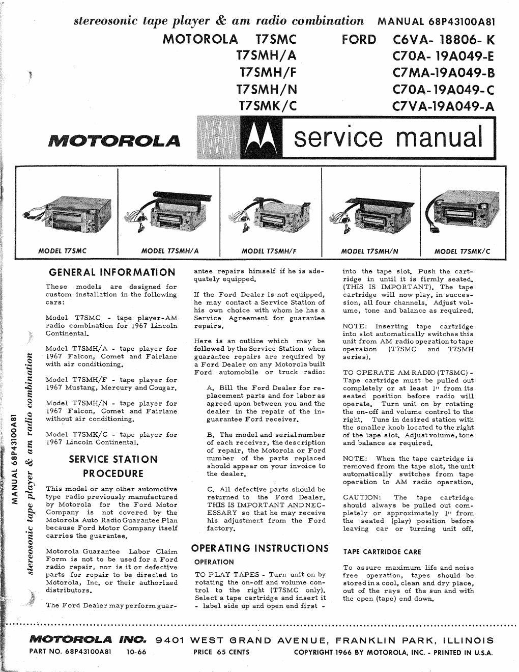
stereosonic tape player & am radio combination MANUAL 68P43100A81
MOTOROLA T7SMC

T7SMH/A

3, 7 T7SMH/F
T7SMH/N

T7SMK/C

FORD C6VA- 18806- K
C7OA- l9A049-E
C7 MA-T9A049-B
C7OA- I9A049- C
C7VA-I9A049-A

MOTOROLA

MODEL T7 SMC

MODEL T7SMH/A

MODEL T7SMH/F

MODEL T7SMH/N

W

MANUAL 68P43100A8'I


stereosonic tape player & am radio combination

GENERAL INFORMATION

These models are designed for
custom installation in the following
cars:

Model TTSMC - tape player-AM
radio combination for 1967 Lincoln
Continental.

Model T7SMH/A - tape player for
1967 Falcon, Comet and Fairlane
with air conditioning.

Model T7SMH/F - tape player for
1967 Mustang, Mercury and Cougar.

Model TTSMH/N - tape player for
1967 Falcon, Comet and Fairlane
without air conditioning.

Model TTSMK/C - tape player for
1967 Lincoln Continental.

SERVICE STATION
PROCEDURE

This model or any other automotive
type radio previously manufactured
by Motorola for the Ford Motor
Company is not covered by the
Motorola Auto Radio Guarantee Plan
because Ford Motor Company itself
carries the guarantee.

Motorola Guarantee Labor Claim
Form is not to be used for a Ford
radio repair, nor is it or defective
parts for repair to be directed to
Motorola, Inc. or their authorized
distributors.

The Ford Dealer may perform guar-

antee repairs himself if he is ade-
quately equipped.

Li the Ford Dealer is not equipped,
he may Contact a Service Station of
his own choice with whom he has a.
Service Agreement for guarantee
repairs.

Here is an outline which may be
followed by the Service Station when
guarantee repairs are required by
a Ford Dealer on any Motorola built
Ford automobile or truck radio:

A. Bill the Ford Dealer for re-
placement parts and for labor as
agreed upon between you and the
dealer in the repair of the in-
guarantee Ford receiver.

B. The model and serialnumber
of each re ceiver, the description
of repair, the Motorola or Ford
number of the parts replaced
should appear on your invoice to
the dealer.

C. All defective parts should be
returned to the Ford Dealer.
THIS IS IMPORTANT AND NEC-
ESSARY so that he may receive
his adjustment from the Ford
factory.

OPERATING INSTRUCTIONS
OPERATION

TO PLAY TAPES - Turn unit on by
rotating the on-off and volume con-
trol to the right (T7SMC only),
Select a tape cartridge and insert it
- label side up and open end first -

into the tape slot. Push the cart-
ridge in until it is firmly seated.
(THIS IS IMPORTANT), The tape
cartridge will now play, in succes-
sion, all four channels. Adjust vol-
ume, tone and balance as required.

NOTE: Inserting tape cartridge
into slot automatically switches this
unit from AM radio operation to tape
operation (TTSMC and T7SMH
series).

TO OPERATE AM RADIO (T7SMC) -
Tape cartridge must be pulled out
completely or at least 1" from its
seated position before radio will
operate. Turn unit on by rotating
the on-off and volume control to the
right. Tune in desired station with
the smaller knob located to the right
of the tape slot. Adjustvolume, tone
and balance as required.

NOTE: When the tape cartridge is
removed from the tape slot, the unit
automatically switches from tape
operation to AM radio operation.

CAUTION: The tape cartridge
should always be pulled out com.
pletely or approximately 1" from
the seated (play) position before
leaving car or turning unit off.

TAPE CARTRIDGE CARE

To assure maximum life and noise
free operation, tapes should be
storedina cool, clean and dry place,
out of the rays of the sun and with
the open (tape) end down.

MODEL T7SMK/C

MOTOROLA INC.
PART No. 68P43100A81 10-66

9401 WEST GRAND AVENUE, FRANKLIN PARK. ILLINOIS
PRICE 65 CENTS COPYRIGHT I966 BY MOTOROLA, INC. - PRINTED IN U.S.A.

Page 2

TAPE PLAYER DRIVE & HEAD
POSITIONING

The View shown below is one looking
into the tape player from the front
with a tape cartridge inserted and
operating.

When the tape cartridge is inserted
into the tape slot and with the unit
turned on, the radio-tape switch (on
radio-tape models) switches the in-
put of the audio system from the
radio circuitry to tape pre-amp cir-
cuitry. At the same time, the front
of the tape cartridge activates a
micro- switch which, in turn, turns
on the tape motor.

The drive belt on the motor shaft
drives the flywheel causing it to
rotate. The flywheel shaft(capstan)
which presses the tape against the
rubber pressure roller (inside the
cartridge) drives the tape. The tape

RADIO - TAPE SWITCH
(0N APPLICABLE MOD ELS)

TAPE GUIDE
BRACKET


DIRECTION OF
TAPE TRAVEL


TRACK SWITCH

CONDUCTIVE
STRIP

TRANSFER PIN

FLYWHEEL

K1

TRAC K 3
TRAC K 4
TRAC K 5
TRAC K 6
TRACK
TRAC K 8

guide bracket keeps the tape from
riding up and down the head,

Since the pre-recordedtape has four
dual channel programs (8 tracks),
the head has to be moved to four
different height positions with re-
spect to the tape, The sequence of
head movement is as follows:

Tracks 1 and 5
Tracks 2 and 6
Tracks 3 and 7
Tracks 4 and 8

Tracks 1 and 5 (return to original
tracks)

The positioning of the head can be
accomplished either manually or
automatically. Manual positioning
is accomplished whenever the chan-
nel selector switch (on volume con-
trol shaft) is pushedinand released.
The momentary shorting of this

RUBBER PRESSURE ROLLER
(INSIDE TAPE CARTRIDGE)

TAPE HEAD (SHOWN
USING TRACKS'I Ii 5)

Z

TAPE DRIVE AND HEAD POSITIONING

switch returns one end of the sole-
noidwinding to ground. The resultant
magnetic field in the solenoid pulls
in the solenoid's spring loaded shaft
for an instant; when the shaft returns
to its original position, it detents the
ratchet end of the cam shaft to its
next position, In contact with the
irregularly shaped cam is the tape
head transfer pin (located beneath
the head) which moves the head up
or down.

Automatic positioning of the head to
the next dual channel program is
accomplished by the tape itselfwhen
the end of a program is reached.
The pre-recorded tape has, at the
end of the recorded programs, a
strip of conductive tape which shorts
out the switch track which is in
contact with the tape at all times.
This switch is wired inparallelwith
the channel selector switch which
starts the same actionthat occurred
with the channel selector switch was
activated,

DRIVE BELT TAN


MICRO-SWITCH

TING ARM

SOLENOID

:n1927