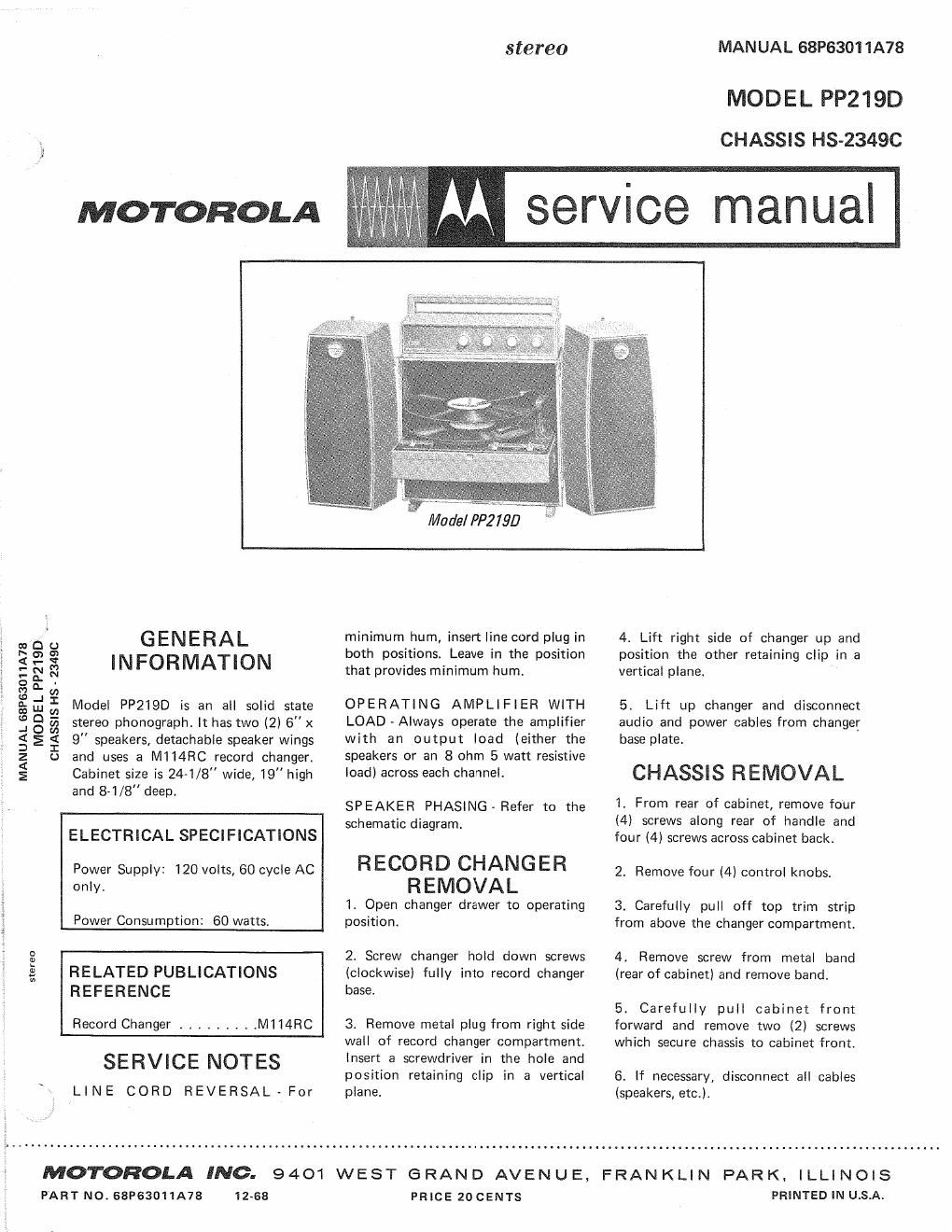
Motorola pp 219 d service manual

This is the 4 pages manual for motorola pp 219 d service manual.
Read or download the pdf for free. If you want to contribute, please mail your pdfs to info@audioservicemanuals.com.

Page: 1 / 4
left right
motorola pp 219 d service manual

Extracted text from motorola pp 219 d service manual (Ocr-read)


Page 1

stereo MANUAL 68P63011A78

MOD E L PP219D
CHASSIS HS-2349C

M service manual

MOTOROLA

stereo

MOTOROLA INC.

PART NO. 63P63011A73

and 8-1/8" deep,

ELECTRICAL SPECIFICATIONS

Power Supply: 120 volts, 60 cycle AC
only.

Power Consumption: 60 watts.

RELATED PUBLICATIONS
REFERENCE

Record Changer ......... M1 I4FIC

SERVICE NOTES

LINE CORD REVERSAL-For

12~68

SPEAKER PHASING » Refer to the
schematic diagram.

RECORD CHANGER
REMOVAL

1. Open changer drawer to operating
position.

2. Screw changer hold down screws
(clockwise) fully into record changer
base.

3. Remove metal plug from right side
wall of record changer compartment.
Insert a screwdriver in the hole and
position retaining clip in a vertical
plane,

9401 WEST GRAND AVENUE, FRANKLIN PARK.

PRICE 20 CENTS

a filo GENERAL minimum hum, insertline cord plug in 4. Lift right side of changer up and
is ch as both positions. Leave in the position position the other retaining clip in a
gE E INFORMATION that provides minimum hum. vertical plane. '

O 0. ,

M a:

Eda Model PP2IQD is an all solid state OPERATING AMPLIFlER WITH 5. Lift up changer and disconnect
j 8 a stereo phonograph. It has two (2) 6" x LOAD ~ Always operate the amplifier audio and power cables from changer
g E E 9" speakers, detachable speaker wings with an output load (either the base plate.

a o and uses a M114RC record changer, Speakers 0" an 8 ohm 5 watt resistive

5 Cabinet size is 24-1/8" wide, 19" high load) across each channel. CHASSIS R EMOVAL

1. From rear of cabinet, remove four
(4) screws along rear of handle and
four (4) screws across cabinet back.

2. Remove four (4) control knobs.

3. Carefully pull off top trim strip
from above the changer compartment.

4. Remove screw from metal band
(rear of cabinet) and remove band.

5. Carefully pull cabinet front
forward and remove two (2) screws
which secure chassis to cabinet front.

6. If necessary, disconnect all cables
(speakers, etc.).

I L LI N OI S
PRINTED IN U.s.A.