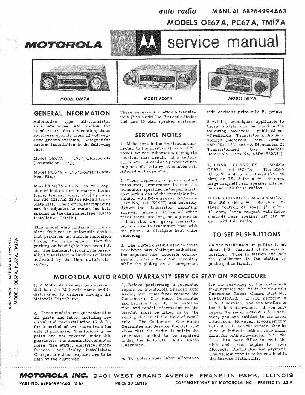
Motorola pc 67 a service manual

This is the 8 pages manual for motorola pc 67 a service manual.
Read or download the pdf for free. If you want to contribute, please mail your pdfs to info@audioservicemanuals.com.

Page: 1 / 8
left right
motorola pc 67 a service manual

Extracted text from motorola pc 67 a service manual (Ocr-read)


Page 1

MOTOROLA

auto radio

MANUAL 68P64994A63

MODELS OE67A, PC67A, TMI7A

service manual

MODEL 0567 A

MODEL PC67 A

MODEL TMI7A

GENERAL INFORMATION

Automotive type
supe rheterodyne AM

all- transistor
radios for

These receivers contain 6 transis-
tors (7 in Model TMlTA) and z diodes
and use 40 ohm speaker systems.

side contains primarily B- points.

Servicing techniques applicable to
these models can be found in the

standard broadcast reception; these following Motorola publications:
receivers operate from 12 voltneg- SERVICE NOTES HProfitable Transistor Radio Ser-
ative ground systems. Designedfor vicingvl (Motorola Part Number

custom installation in the following
cars:

Model OE67A -
(Dynamic 88, Etc.).

1961 Oldsmobile

Model PCé7A - 1967 Pontiac (Cata-
lina, Etc.).

Model TM17A - Universal type cap-
able of installation in many vehicles
(cars, trucks, boats, etc.) by using
the AK-ZZ3, AK-230 or KMSST trim-
plate kits. The control shaft spacing
can be adjusted to match the hole
spacing in the dashpanel (see Radio
Installation Detail" ).

This model also contains the Lum~
alert feature; an automatic device
that produces an audible indication

2. These models are guaranteedfor
all parts and labor. including re-
moval and revinstallation (R 8: R),
for a period of two years from the
date of purchase. The following re-
pairs are not covered under this
guarantee: the elemination of motor
noise, tire static, electrical inter-
ference and ,faulty installation.
Charges for these repairs are to be
paid by the customer.

1. Make certain the "A leadis con-
nected to the positive (+) side of the
power source, otherwise, damage to
receiver may result. If a battery
eliminator is used as apower source
in place of a battery, it must be well
filtered and regulated.

2. When replacing a power output

transistor, remember to use the
transistor specified inthe parts list;
coat both sides of the transistor in-
sulator with DC-4 grease (Motorola
Part No. 11M490487) and securely
tighten the transistor mounting
screws. When replacing all other
transistors, use longnose pliers as
a heat sink, i.e., grasp transistor
leads close to transistor base with
the pliers to dissipate heat while
soldering.

tion and model information on the
booklet must be filled in by the
selling dealer at the time of retail
sale. The Customers Car Radio
Guarantee and Service Bookletmust
show that the radio is within the
guarantee period to be repaired
under the Motorola Auto Radio
Guarantee,

4. To obtain your labor allowance

68P600 11A53) and A Discussion Of
Transistorized Car Radios
(Motorola Part No. 68P64980A5 l).

4. REAR SPEAKERS - Models
OE67A and PC67A - The RS-9
(6" x 9" - 40 ohm), RS-10(6" - 40
ohm) or RS- 12 (6" x 9" - 40 ohm,
large magnet) rear speaker kits can
be used with these radios.

REAR, SPEAKER - Model TMl7A -
The RS-S (6" x 9" - 40 ohm with
fader control) or RS-ll (6" X9" -
40 ohm, large magnet with fader
control) rear speaker kit can be
used with this radio.

TO SET PUSHBUTTONS

m
<" 5 through the radio speaker that the
g E parking or headlights have been left 3. The plated chassis used in these Unlock pushbutton by pulling it out
3 I- on. The Lumalert circuitryis basic- receivers have plating onbothsides; about 1/2" forward of its normal
g g: ally atransistorizedaudio oscillator the exposed side (opposite compo- position. Tune in station and lock
3 S activated by the light switch cir- nents) contains the actual circuitry the pushbutton to the station by
2 g cuitry. while the plating on the component pushing it in firmly.
E a
s 5 MOTOROLA AUTO RADIO WARRANTY SERVICE STATION PROCEDURE

0 l. AMotorola Branded Modelis one 3. Before performing a guarantee for the servicing of the customers
.2 .3 that has the Motorola name and is re air on a Motorola Branded Auto in E a distributed to dealers through the Radio, you must first receive the Guarantee Labor Claim, Part No.
I; 0 Motorola Distributor, Customers Car Radio Guarantee 68P60016A30. If you perform a
g E and Service Booklet. The installa- R in R service, you are entitled to
S

the R & R allowance. If you only
repair the radio without R t: R ser-
vice, you are entitled to the labor
allowance. However, ifyouperform
both R 3: R and the repair, then be
sure to indicate both on your claim
form for both allowances. After the
form has been filled in, mail the
pink and green copies to your
Motorola Distributor for payment.
The yellow copy is to be retained in
the Service Station file.

MOTOROLA INC.
, PART No.68P64994A63 2-57

9401 WEST GRAND AVENUE, FRANKLIN PARK,
PRICE 20 CENTS

I LLI N O I S
COPYRIGHT I967 BY MOTOROLA INC. - PRINTED IN U.S.A.

Page 2

5. Defective parts for guarantee re-
pairs made are to be sent to your
Motorola Distributor for free re-
placement supported with the defec-
tive parts return tag, Part Number
54P59l808.

basis to

can perform
guarantee

6. Only these service stations auth-
orized by their Motorola Distributor
repairs within the
period on a no- charge
If you are

the customer.

ALIGNMENT

not an Authorized Motorola Auto
Radio Service Station and you are
interested in handling this service,
please contact your Motorola Dis-
tributor for complete details.

Connect an output meter across the speaker voice coil. Set volume to maximum and tone to treble. Atten-
uate signal generator output to maintain lwatt (6,33 volts across a 40 ohm load) on output meter at all times.

GENERATOR
GENERATOR FREQUENCY
STEP CONNECTION (400 cycle 30% mod) TUNER SET TO ADJUST REMARKS
1F ALIGNMENT
1, To collector of 262.5Kc Hi end stop 1, 2, 3 Adjust for maximum,
RF amp thru 8: 4
.lmf and chassis
RF ALIGNMENT
2, Antenna recept- lélOKc Hi end stop 5, 6 8n 7 Adjust for maximum.
acle thru dummy
(see Figure)
NOTE: D0 not perform Steps #3, #4. #5 and #6 unless the tuner has been tampered with or associated
components have been replaced. If necessary, remove the escutcheon, dial background and the
pilot light socket to expose the core screws. Before proceeding with Step #3, back the tuning cores
as far as possible out of the Coils to eliminate their effect on trimmer adjustments.
3. Antenna recept- 1610K: Hi end stop 5, 6, 7 Adjust for maximum.
acle thru dummy S: 8
(see Figure)
4. leOKc Tuner carriage 9, 10,711. Adjust for maximum,
(pushbucton models) .285 from hi 3: 12
end stop
5. " lélOKc Hi and stop 5, 6, 7 Adjust for maximum.
8: S
6. Repeat Steps #4 and #5 until no further increase; Step #5 should be last step. Then cement core
screws in place.
ANTENNA TRIMMER
7. ---- ---- Weak station 8 Adjust for maximum with
around 1400Kc car radio installed in car
and antenna fully extended.
0 O
REAR VIEW 0
O O
Q (3D V; 0 IF ALIGNMENT
-- DETAiL
ANT TOP BOT TOP BOT
RECEPT 3 0 09 09
--.
PLUG TO FIT RECEIVER
____.___ mum thtmcu
J. 50?; T0 mam
1051mm _ -- -. ANTENNA
CECE: "-""y-1
I . mm 5mm cm
FRONT VIEW P L.-- ___3 must BE ATTACHED
TO PLUG

ALIGNMENT LOCATION DETAIL

DUMMY ANTENNA DETAIL