Motorola m 113 rc service manual

This is the 12 pages manual for motorola m 113 rc service manual.
Read or download the pdf for free. If you want to contribute, please mail your pdfs to info@audioservicemanuals.com.

Page: 1 / 12
left right
motorola m 113 rc service manual

Extracted text from motorola m 113 rc service manual (Ocr-read)


Page 1

MOTOROLA

OPERATING

INSTRUCTIONS

' AUTOMATIC PLAYING

l. Raise record stabilizer (54) and
swing it away from spindle.

2. Turn stylus selector to "78" for

78 RPM records or to "LP" for all

other records.

3. Slide Speed control to 16, 33, 45
or 78.

4. Slide set-down control to size of
records to be played: 12. 10 or 7.

record changers

MODELS MIIIRC, MITZRC,

MANUAL 68P63:OIOA88

MIIBRC,

MII4RC

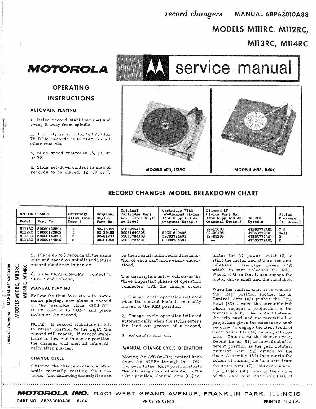
7 M service manual

MODELS MIII, "2R6

MODELS MII3, II4RC

RECORD CHANGER MODEL BREAKDOWN CHART

Original Cartridge With Diamond LP

RECORD CHANGER Cartridge Original Cartridge Part LP-Diamond Stylus Stylus Part No. Stylus
Illus (See Stylus No. (Incl Styli (Not Supplied As (Not Supplied As 45 RPM Pressure

lodel Put No. Page ) Part No. At Left) Original Equip.) Original Equip.) Spindle (In Grams)
ullmc 59E60122301 4 92-15085 59C62954A01 -- 92-150175 473637721101 7-9
11112120 591:60122302 4 92-2945s 590616401103 590516401106 92-294115 41B-‚¬3772A01 9-11
Liliane 591860144301 5 92-31235 59C63784A03 590637841101 92412135 475637721101 ~ 2
unmc 59E60144302 5 92-31mm 59C63184A01 59cs37s4A01 - 47363772Aol 2

5. Place up to 6 records allthe same

MII3RC, MIMRC

MANUAL 68P63010A88

MODELS MIIIRC, MII2RC,

record changers

OFF"

NOTE:

MANUAL PLAYING

noNu

cally after playing .

CHANGE CYCLE

size and speed on spindle and return
record stabilizer to center.

6. Slide "REJ-ON-OFF control to
'IREJ" and release.

Follow the first four steps for auto-
matic playing, now place a record
on the turntable, slide
control to
stylus on the record.

"REJ - ON-
and place

If record stabilizer is left
in raised position to the right, the
record will repeat. If record stabi-
lizer is lowered in center position,
the changer will shut off automati-

Observe the change cycle operation

table.

MOTOROLA INC.

PART NO. 68P63OIOA38

8-66

while manually rotating the turn-
The following description can

9401

be then readily followed and the func-
tion of each part more easilyunder-
stood.

The description below will cover the
three important phases of operation
connected with the change cycle:

1. Change cycle operation initiated
when the control knob is manually
moved to the BET position.

2. Change cycle operation initiated
automatically when the stylus enters
the lead out groove of a record.

3. Automatic shut-off.

MANUAL CHANGE CYCLE OPERATION

Moving the Off-On-Rej control knob
from the OFFI through the ON"
and over to the "REE position starts
the following chain of events. Inthe
"On" position, Control Arm (82) ac-

PRICE 35 CENTS

tuates the AC power switch (8) to
start the motor and at the same time

releases

Disengage

Lever

(78)

which in turn releases the Idler
Wheel (18) so that it can engage the
motor drive shaft and the turntable.

Whenlthe control knob is movedinto
the Rej position another tab on
Control Arm (82) pushes the Trip
Pawl (33) toward the turntable hub
which engages a projection on the
turntable hub. The Contact between
the trip pawl and the turntable hub
projection gives the necessary push
required to engage the first tooth of
Gear Assembly (34) causing it to ro-

tate.

This starts the change cycle.

Detent Lever (57) is movedout ofits
detent position as the gear rotates.
Actuator Arm (52) driven by the
Gear Assembly (34) then starts the
action of raising the tone arm from
the Rest Post (1 17) .This occurs when
the Lift Pin (90) rides up the incline
of the Cam Arm Assembly (84); at

WEST GRAND AVENUE, FRANKLIN PARK. ILLINOIS

PRINTED IN U.S.A.

Page 2

the sgne time, the Cam Arm Pin
(89) pushes down the clutch Spring
pad (part of 84) against the Index
Plate (96) causing the Tone Arm to
be carried back against the raised
portion of the Rest Post (117). Near
the end of the movement of the Cam
Arm Assembly (84), the Ejector Link
(85) actuates the record push-off
mechanism in the Spindle (31)
causing a record to drop onto the
turntable. Since the RecordEjector
(part of 31) is the same thickness
as one record, only 1 record will
drop.

Continuing with rotation of the Gear
Assembly (34), the Detent Lever (57)
is released from its travel along the
lip on the underside ofthe gear. The
Trip Pawl Assembly (33) isthenre-
set to its n0n>trlp position. As the
Actuator Arm (52) starts to travel
in the reverse direction, the clutch
pad against the Index Plate (96)
moves the raised tone arm over the
record. The inward travel of the
Tone Arm is limited by the steps on
the Index Plate (96) striking the stud
located on the end of Selector Lever
Assembly (79). Further movement
of the Cam Arm Assembly (84)
allows the Lift Pin (90) to drop
lowering the Tone Arm and Stylus.
The Gear Assembly continues to ro-
tate into the detent position at which
point the change mechanism comes
to rest.

AUTOMATIC CHANGE CYCLE OPERATION

This change cycle operates on the
velocity trip principle. The change
cycle is started by the faster inward
motion of the tone arm when the sty-
lus enters the trip grooves at the end

of a record.

The Tone Arm (40), Index Plate (96)
and Trip Link (87) are connected so
that they move in unison. As the tone
arm nears the end of a record (ap-
proximately 2- 1/2" from the
spindle), Index Plate (96) pushes
Trip Link (87) against the Trip Pawl
Assembly (33) which in turn is
pushed toward the turntable hub. As
the stylus advances one groove
closer to the spindle witheach revol-
ution, the Trip Pawl is not advanced
quite far enough to fully engage with
the projection on the turntable hub.
With each revolution, the trip pawl
is pushed back so that the next revol-
ution of the turntable will not cause
cycling. When the stylus enters the
widely spaced lead out grooves of
the record, the Trip Link (87)pushes
the Trip Pawl Assembly (33) in far
enough in one revolution to engage
with the projection on the turntable
hub giving the necessary push re-
quired to engage the gear assembly
starting the change cycle as before.

AUTOMATIC SHUT-OFF

When the last record on the spindle
drops into playing position, the Re-
cord Stabilizer Arm (54) drops about
1" below its normalpcsition (i. e. its
position with a record on the
spindle). This difference invertical
position of the stabilizing arm actu-
ates the automatic shut-off action.
At the end of the last record, the
Lock Lever (part of Stabilizer Guide
Assembly - 32) is held in the down
position by the Stabilizer Shaft (5 8).
The lock lever is coupled with a
spring (91) to a Hook Lever (part of
92) that restricts the movement of

the Index Plate (96) thereby pre-
venting the tone arm from moving
in toward the spindle as it normally
would. Since it is restricted to any
lateral movement, it simply drops
on the rest post.

During the same period, Shut-Off
Link (94) pulls the Control Arm(82)
to actuate the AC Power Switch (8)
and positions Disengage Lever (78)
to restrict the Vmovement ofthe Idler
Yoke (4) so that the Idler Wheel(18)
is retracted. At this point, the gear
assembly has returned to the out-of-
cycle position and the motor power
is shut off.

MAI NTE NA NCE
ADJUSTMENTS

TONE ARM HEIGHT ADJUST-
MENTS - The tone arm height is
adjusted by means of the Height Ad-
justing Screw. To raise the tone
arm height, turnthis screw counter-
clockwise. To lower the tone arm,
turn clockwise. Adjustment should
be made so that the stylus will clear
the recommended stack of 6 records
during the change cycle without hit»
ting the underside of the records
loaded on the spindle.

SET DOWN ADJUSTMENT - Turn
the Set Dow-n Adjustment Screw
clockwise to position stylus in to-
ward spindle, counter-clockwise to
position stylus away from spindle.
When properly adjusted, the stylus
should land 1/8 in from the edge of
a standard 10 record. lithe adjust-
ment is made correctly on a 10"
record, the 7" and 12" landing will
be correct also.

CHANGE CYCLE PARIS LOCATION