Motorola ht 618 ch service manual

This is the 16 pages manual for motorola ht 618 ch service manual.
Read or download the pdf for free. If you want to contribute, please mail your pdfs to info@audioservicemanuals.com.

Page: 1 / 16
left right
motorola ht 618 ch service manual

Extracted text from motorola ht 618 ch service manual (Ocr-read)


Page 1

color
television

SUPPLEMENT TO TS-921A

SERVICE MANUAL,
PART NO. 68P65155AOI

SUPPLEMENTARY MANUAL 68P65I 3OAO7

TV CHASSIS D2OTS-921 & E20TS-92I
RADIO CHASSIS THS-67225-C
~ 3 MODELS HT6I7CH, CN, CW & HT6I8CH, CN, CW

, , my,
TV CHASSIS D2OTS-92I 8; E20TS-92I

W
color

SUPPLEMENT TO TS-921A

RADIO CHASSIS THS-67225-C

MODELS HT617CH, CN, CW & HTbIBCH, CN, CW

television

sum mum,
rm No menu

MOTOROLA

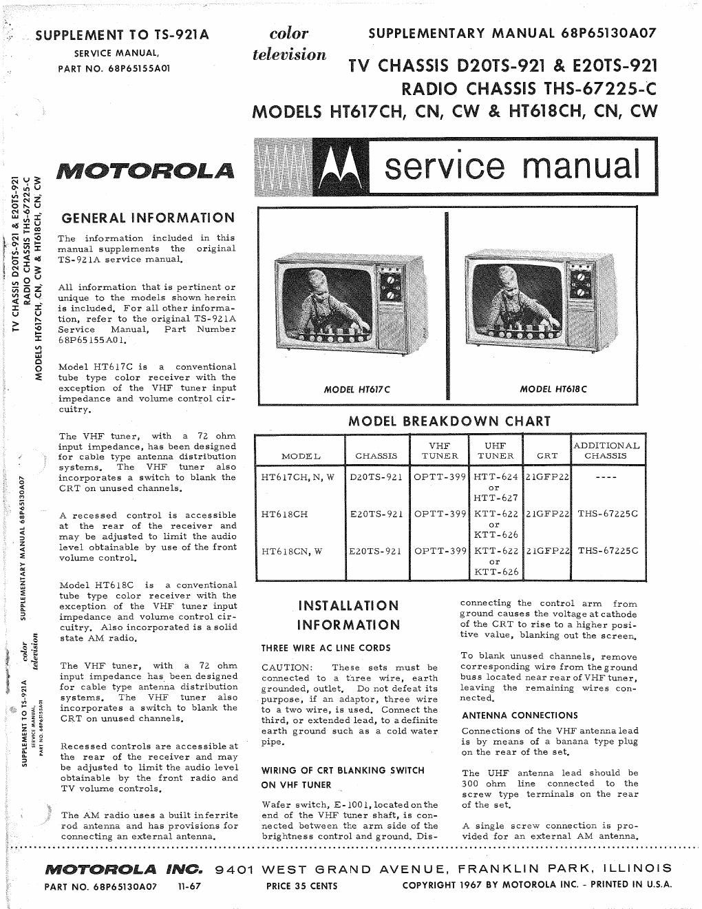
GENERAL INFORMATION

The information included in this
manual supplements the original
TS-921A service manual,

All information that is pertinent or
unique to the models shown herein
is included, For all other informa-
tion, refer to the original Ts-921A
Service Manual, Part Number
68P65155A0 1.

Model HT617C is a conventional
tube type color receiver with the
exception of the VHF tuner input
impedance and volume control cir-
cuitry.

cuitry. Also incorporated is a solid
state AM radio.

The VHF tlmer, with a 72 ohm
input impedance has been designed
for cable type antenna distribution
systems. The VHF tuner also
incorporates a switch to blank the
CRT on unused channels.

Recessed controls are accessible at
the rear of the receiver and may
be adjusted to limit the audio level
obtainable by the front radio and
TV volume controls.

The AM radio uses a built inferrite
rod antenna and has provisions for
connecting an external antenna.

MODEL H1617 C

MODEL HT618 C

MODEL BREAKDOWN CHART

INFORMATION

THREE WIRE AC LINE CORDS

CAUTION: These sets must be
connected to a three wire, earth
grounded, outlet, Do not defeat its
purpose, if an adaptor, three Wire
to a two wire, is used. Connect the
third, or extended lead, to adefinjte
earth ground such as a cold water
pipe.

WIRING OF CRT BLANKING SWITCH
ON VHF TUNER

Wafer switch, 12-1001, located onthe
and of the VHF tuner shaft, is con-
nected between the arm side of the
brightness control and ground. Dis-

The VHF tuner, with a 72 ohm
input impedance, has been designed VHF UHF ADDITIONAL
«' for cable type antenna distribution MODEL CHASSIS TUNER TUNER CRT CHASSIS
systems, The VHF tuner also
'5 incorporates a switch to blank the HT617CH,N,W D20TS-921 OPTT-399 HTT-624 ZIGFPZZ ----
g CRT on unused channels. or
E HTT-627
a
s A recessed control is accessible HTolSCH E20TS-9Zl OPTT-399 KIT-62.2 ZlGFPZZ THS-67225C
: at the rear of the receiver and or
§ may be adjusted to limit the audio KTT-626
3 level obtainable by use of the front
2 volume control HTGIBCN,W EZOTS-921 OPTT-399 KTT-éZZ ZIGFPZZ THS-67225C
>- ' or
E KTT-ézé
5 Model HTGISC is a conventional
5 tube type color receiver with the
§ exception of the VHF tuner input INSTALLATION connecting the control arm from
a impedance and volume control cir- ground causes the voltage at cathode

of the CRT to rise to a higher posi-
tive value, blanking out the screen.

To blank unused channels, remove
corresponding wire from the ground
buss located near rear of VHF tuner,
leaving the remaining Wires con-
nected,

ANTENNA CONNECTIONS

Connections of the VHF antenna lead
is by means of a banana type plug
on the rear of the set,

The UHF antenna lead should be
300 ohm line connected to the
screw type terminals on the rear
of the set,

A single screw connection is pro-
vided for an external AM antenna,

MOTOROLA INC. 9401 WEST e RAN D AVEN U E, FRAN KLI N PAR K, I LLI NOI s
PARY NO. 68P65130A07 11-67 PRICE 35 CENTS COPYRIGHT 1967 BY MOTOROLA INC. - PRINTED IN U.S.A.

Page 2

AM RADIO ALIGNMENT PROCEDURE

Use an isolation transformer between the power line and the receiver. If not available, connect low side of
generator to B- through a .1 mfcapacitor. Connect a low range output meter across speaker voice coil and
set volume control to maximum. Attenuate generator output to maintain 50 milliwatts on output meter to
prevent overloading (50 milliwatts is .64 volts across an 8 ohm load).

GENERATOR
GENERATOR FREQUENCY
STEP CONNECTION (400 cycle mod) GANG SETTING ADJUST REMARKS

IF ALIGNMENT

1. Radiation loop* 455Kc Fully open 1, 2, 3 8: 4 Adjust for maximum.
RF ALIGNMENT

2, Radiation loop* 535Kc Fully closed 7 Adjust for maximum.

3. Radiation loop* 1620Kc Fully open 5 Adjust for maximum.

4. Radiation loop* 1400Kc Tone for maximum 6 Adjust for maximum.

at 1400Kc
*Connect generator output across 5" diameter, 5-turn loop and couple inductively to receiver loop. Keep
radiation loop approximately 24" from ferrite antenna.
TO L1 IF IF
ANT BOT 90 TOP BOT TOP
we
TRIM
If 1_-I_ -J
' O
Q-
c2 _1 0
ON ANT
3 ASSEM I
03c (l:__l_fi fl um;
TRIM OSC CORE
ALIGNMENT POINTS

02

PARTS LOCATION