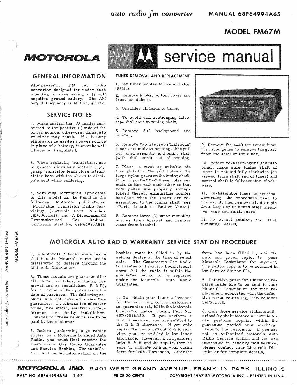
Motorola fm 67 m service manual

This is the 8 pages manual for motorola fm 67 m service manual.
Read or download the pdf for free. If you want to contribute, please mail your pdfs to info@audioservicemanuals.com.

Page: 1 / 8
left right
motorola fm 67 m service manual

Extracted text from motorola fm 67 m service manual (Ocr-read)


Page 1

MANUAL 68Pb4994A65

MODEL FM67M

MOTOROLA

GENERAL INFORMATION

All-transistor FM car radio
converter designed for under-dash
mounting in cars having a 12 volt
negative ground battery. The AM
output frequency is 1400Kc, i3OKC,

SERVICE NOTES

1. Make certain the "A lead is con-
nected to the positive (+) side of the
power source, otherwise, damage to
receiver may result. If a battery
eliminator is used as apower source
in place of a battery, it must be well
filtered and regulated.

2. When replacing transistors, use
long-nose pliers as a heat sink,i,e,,
grasp transistor leads close totran-
sistor base with the pliers to dissi-
pate heat while soldering.

3, Servicing techniques applicable
to this model can be found in the
following Motorola publications:
"Profitable Transistor Radio Ser-
vicingH (Motorola Part Number
68P60011A53) and A Discussion Of
Transistorized Car Radios"
(Motorola Part No. 68P64980A51).

MOTOROLA AUTO

l. A Motorola Branded Modelis one
that has the Motorola name and is
distributed to dealers through the
Motorola Distributor.

auto radio fm converter

MANUAL 68P64994A65

MODEL FM67M

TUNER REMOVAL AND REPLACEMENT

1. Set tuner pointer to low end stop
(88Mc).

2. Remove knobs, bottom cover and
front escutcheon.

3. Unsolder all leads to tuner.

4. To avoid dial restringing later,
tape dial cord to tuning shaft.

5. Remove dial
pointer.

backg round and

6. Remove two (2) screws that mount
tuner assembly to housing, thenpull
out tuner assembly and tuning shaft
(with dial cord) out of housing.

7, Place a rivet or suitable pin
through both of the 1/8" holes inthe
large nylon gears on the tuning shaft;
it is important that these holes re-
main in line with each other so that
both gears are properly spring-
loaded thereby eliminating pointer
backlash when the gears are re-
assembled to the tuning shaft (see
"Parts Location - Bottom View").

8. Remove three (3) tuner mounting
screws from bracket and remove
tuner from bracket.

RADIO WARRANTY SERVICE

booklet must be filled in by the
selling dealer at the time of retail
sale. The Customer's Car Radio
Guarantee and Service Booklet must
show that the radio is within the

9. Remove the 4-40 set screw from
the nylon gears to remove the gears
from the shaft on the tuner.

10. Before re~assemblying gears to
tuner, make sure tuning shaft of
tuner is rotated fully clockwise (as
Viewed from shaft end of tuner) and
control shaft is fully counter-clock-
wise.

11. Re-assemble tuner to housing,
reversing the procedure used to
remove it, then remove rivet or pin
from large nylon gears after mesh-
ing large and small gears.

12. To re-set pointer, see "Dial
Stringing Detail".

STATION PROCEDURE

form has been filled in, mail the
pink and green copies to your
Motorola Distributor for payment.
The yellow copy is to be retained in
the Service Station file.

2. These models are guaranteedfor guarantee period to be repaired ,
all parts and labor, including re- under the Motorola Auto Radio 5. Defective parts for guarantee re-
> moval and re-installation (R & R), Guarantee. pairs made are to be sent to your

auto radio f m converter

for a geriod of two years from the
date of purchase. The following re-
pairs are not covered under this
guarantee: the elimination of motor
noise, tire static, electrical inter-
ference and faulty installation,
Charges for these repairs are to be
paid by the customer.

3. Before performing a guarantee
repair on a Motorola Branded Auto
Radio, you must first receive the
Customer's Car Radio Guarantee
and Service Booklet. The installa-
tion and model information on the

4, To obtain your labor allowance
for the servicing of the customers
in-guarantee set, fillinthe Motorola
Guarantee Labor Claim, Part No.
68P60016A30, If you perform a
R 8: R service, you are entitled to
the R E: R allowance, If you only
repair the radio without R 8: R ser-
vice, you are entitled to the labor
allowance. However, if youperform
both R & R and the repair, then be
sure to indicate both on your claim
form for both allowances. After the

Motorola Distributor for free re~
placement supported with the defec -
tive parts return tag, Part Number
5413591808.

6. Only those service stations auth-
orized by their Motorola Distributor
can perform repairs within the
guarantee period ona no-charge
basis to the customer. If you are
not an Authorized Motorola Auto
Radio Service Station and you are
interested in handling this service,
please contact your Motorola Dis-
tributor for complete details.

MOTOROLA INC.
PART NO. 69964994Aes 2-67

9401 WEST GRAND AVENUE, FRANKLIN PARK,
PRICE 20 CENTS

I LLI N O I S
COPYRIGHT 1967 BY MOTOROLA INC. A PRINTED IN U,S.A.

Page 2

ALIGNMENT

GENERAL INFORMATION - The factory alignment is performed with laboratory equipment. The circuits
are quite stable and not ordinarily subject to drift; therefore, before alignment is attempted, the set should
be thoroughly checked for circuit troubles. During alignment, all covers should be in place and securely
tightened (unlessit is impossible to gain access to a test point through the cover). An AM or FM generator
can be used for FM alignment. The test points referred to in the alignment procedure are identified on the
schematic and their physical location shown in the Alignment Detail".

ALIGNMENT CONDITIONS - Input voltage to the receiver 14V DC. During FM alignment the input signal
amplitude must be kept below the limiting level. To check this, change the generator attenuator setting and
note where further increase in input does not increase the output reading. The input signal level must be

attenuated to keep the output below this level.
carefully shielded. If noise Voltage

For the same reason, the signal generator leads must be
onthe generator leads is high enough to cause limiting,

it is impossible

to align the receiver properly because tuning adjustments will show up as variations in the VTVM reading.
To avoid this, the leads must be carefully shielded and kept short.

FM ALIGNMENT USING FM SIGNAL GENERATOR

GENERATOR GENERATOR TUNER OUTPUT
STEP CONNECTION FREQUENCY SET TO INDICATOR ADJUST REMARKS
FM - IF ALIGNMENT

1. Antenna recept- 10.7Mc 108.5Mc VTVM-DC 2.3.4.5, Adjust for maximum positive
acle thru dummy (22.5Kc sweep (high end probe to 6, 7, 8,? output (if possible, observe IF

(see Figure) width, 400cps stop) point A, 8: 10 waveform on scope for best

mod) common to symmetry of curve while

chassis aligning).

2. H H H VTVM- DC 1 Adjust for zero reading on
probe to VTVM; a + or - reading will
point B", be obtained on either side of
common to correct setting. Repeat Steps
chassis #1 and #2 until no further in-

crease; Step #Z should be last
step.
FM - RF ALIGNMENT
3, Antenna recept- 87.5Mc 87.5Mc VTVM-DC 11, 12, 13 Adjust for maximum positive
acle thru dummy (22.5Kc sweep (low end probe to IS: 14 output, Make certain input
(see Figure) width, 400cps point A, signal is below limiting level.
mod) common to
chassis
FM ALIGNMENT USING AM GENERATOR
l. Antenna recept- 10.7Mc 108.5Mc VTVM-DC 2, 3, fl, 5, Adjust for maximum positive
acle thru dummy (no mod) (high end proble to 6,7, 8, 9 output. Make certain input
(see Figure) stop) point "A, & 10 signal is below limiting level.
common to
chassis
2. 10.7Mc 108.5Mc VTVM-DC ) Adjust for zero reading on
(no mod) (high end probe to VTVM; a + or - reading will
stop) point "B", be obtained on either side of
common to correct setting. Repeat Steps
chassis #1 and #2 wt" to furthrr n-
crease; Step a should 1*
step.
FM - RF ALIGNMENT
3. Antenna recept- 87.5Mc 87.5Mc VTVM-DC ll, 12, Adjust for maximum positive
acle thru dummy (no mod) (low end probe to 13 & 14 output. Make certain input
(see Figure) stop) point A, signal is below limiting level.
common to
chassis

I400KC OSCILLATOR ADJUSTMENT

The FM67M is shipped from the factory with the AM oscillator pre-set at 1400Kc and does not require ad-
justment as part of the FM alignment procedure. However, if adjustment is required, proceed as follows:

A. Install the FM67M into the car and make all electrical connections.
B. Adjust the car's antenna height to approximately 30" measured from the mounting surface to the tip.
C. Turn the AM radio on(andturnoffFM67M), tune the AM radio to a weak station around 1400Kc (or to

the frequency recommended in the AM radio Owner's Manual). Adjust the antenna trimmer for maximum
volume.