Motorola cu 622 c service manual

This is the 8 pages manual for motorola cu 622 c service manual.
Read or download the pdf for free. If you want to contribute, please mail your pdfs to info@audioservicemanuals.com.

Page: 1 / 8
left right
motorola cu 622 c service manual

Extracted text from motorola cu 622 c service manual (Ocr-read)


Page 1

SUPPLEMENT NO. 2 television MANUAL 68P65'I35A79
TO TS-918A SERVICE MANUAL,

PART NO. 68P65135A77 CHASSIS TS-918A
MODELS RT606C, CU622C

,r \
L , - - -
I _
N 5'
C5 E k
z
I- E '
5 :§ GENERAL INFORMATION {3
g o . ,
E e z
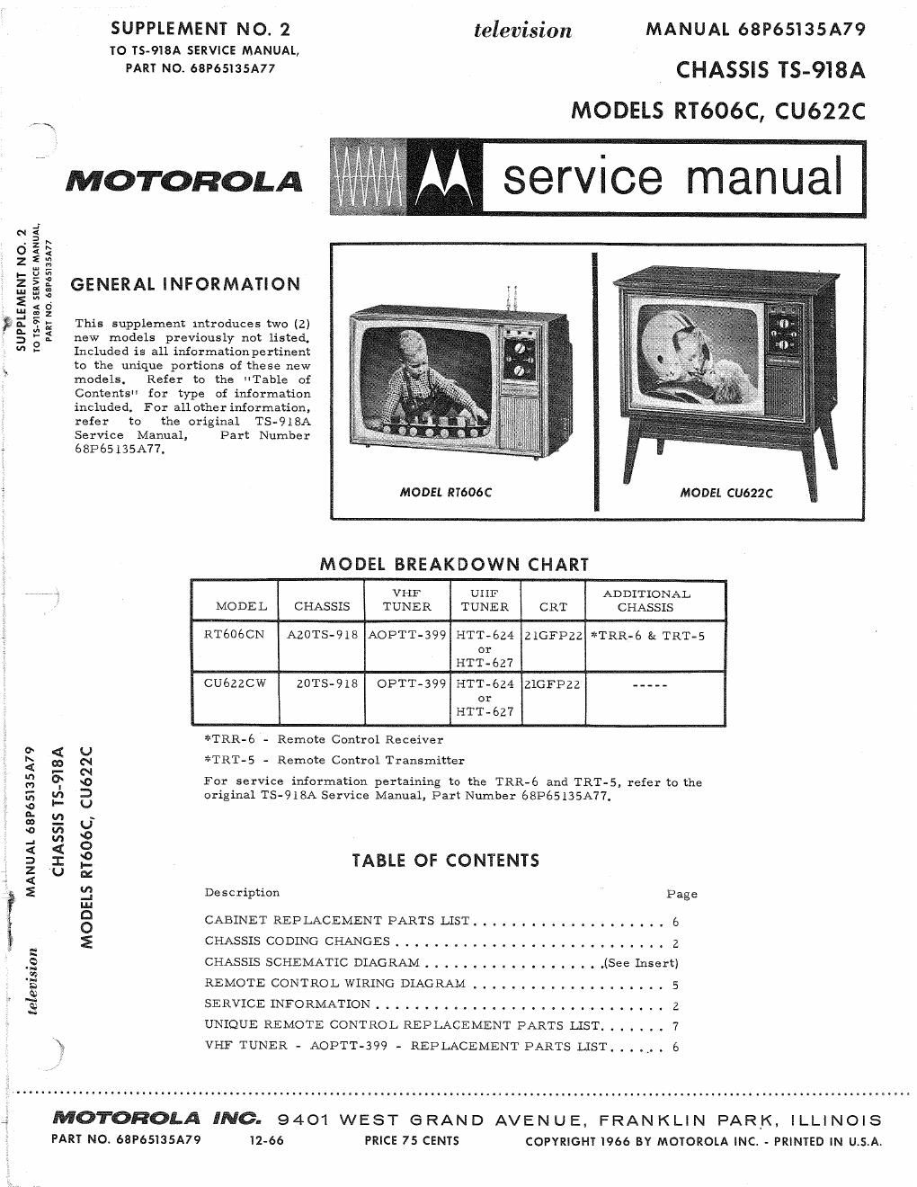
a. i a; This supplement mtroduces two (2)
S 5: new models previously not listed.
" - Included is all informationpertinent
A to the unique portions of these new
models. Refer to the HTable of
Contents" for type of information
included. For all other information,
refer to the original TS918A
Service Manual, Part Number
, 68P65135A77.
MODEL RT606C MODEL CU622C
MODEL BREAKDOWN CHART
, a VHF UHF ADDITIONAL
MODEL CHASSIS TUNER TUNER CRT CHASSIS
RT606CN AZOTS-918 AOFTT-399 HTT-624 ZlGFPZZ *TRR-é & TRT-S
or
HTT-6Z7
CU622CW 20TS-918 OPTT-399 PITT-624 zlGFPZZ -----
or
HIT-627
*TRR-6 - Remote Control Receiver
0 < U ,
I; m N *TRT-S - Remote Control Transmltter
N
g 6"- so For service information pertaining to the TRR-é and TRT-S, refer to the
3 fl 3 original TS-918A Service Manual, Part Number 68P65135A77,
o
n. u) ~
3 «7, g
.n 2 O
<
:a I ,2 TABLE OF CONTENTS
3 U m
E 3 Description Page
Lu
8 CABINETREPLACEMENTPARTSLIST.................... 6
E CHASSISCODINGCHANGES..... ...... .................Z
2
.2 CHASSIS SCHEMATIC DIAGRAM . . . . . . . . . . . . . , . . . . .(See Insert)
E REMOTECONTROLWIRINGDIAGRAM .................... 5
A)
T) SERVICEINFORMATION......... ....... . .2
u
UNIQUE REMOTE CONTROL REPLACEMENT PARTS LIST. . . . . 7
X VI-EF TUNER - AOPTT-399 - REPLACEMENT PARTS LIST 6

3 MOTOROLA INC. 9401 WEST e RAN D AVEN U E, FRAN KLI N PARK, ILLINOIS
PART No. 68P65135A79 12-66 PRICE 75 CENTS COPYRIGHT 1966 BY MOTOROLA INC. - PRINTED IN U.S.A.

Page 2

S
l

T

CHASSIS CODING CHANGES

Chassis Chassis
Coding Chassis Coding Changes Coding Chassis Coding Changes
TS-918A-01 SEE CODING CHANGE 15-05. with 22K in some sets. If replacement is

necessary, replace with original value,
TS-918A-OZ TO IMPROVE PINCUSHION CORREC-
TION: Circuitry feeding correctionvolt- TS-918A-05 RELIABILITY CHANGE: R-szz, 120K,
age to pincushion Corrector assembly has I watt boot filter resistor replaced with a
been slightly revised (see schematic dia- 2 watt resistor.

gram). R-6ZO has been deleted, R-73l
(2.7K) replaced with 1.2K and R-73Z (820 TS-9lSA-06 RELIABILITY CHANGE: Horizontalout-

ohm) added. put tube screen dropping resistor (10K,

10 watt) R-519 changed toa 12.5K,10watt.

TS-918A-03 RELIABILITY CHANGE: R-szz, 120K, Increasing the value of this resistor to
1/2 watt boot filter resistor replacedwith 12.5K improves horizontal output tube

a 1 watt resistor, Also see Coding (éJsé) reliability and will accommodate

Change A-05n. the new horizontal output tube, 6LB6,

TS-918A-O4 TO OBTAIN ADEQUATE 2ND ANODE NOTE: If the 6LBS tube is used in sets
VOLTAGE; Resistor, 11-517 (33K), in coded earlier than A-Ob, the screendrop-

horizontal outputgridbias circuit replaced Ping resistor must be replacedwitha 12.5K

10 watt unit, Part Number 175135834.

El E2
E4 E3 MUTE 81 FUNCTION AUDIO STEP
AFETY AUDIO TUNER DRIVE RELAY (MUTES AUDIO 81 REC OFF RELAY
& BSRITE M'UTE SW MOTOR S [22 P1 & HUE CHANGES - WITH (WIT DUST COVER)

2m

REMOTE
REC TRR6

L700
VERT TOP TILT
COIL

R709
VERT BOT AMP
CONTROL

HORIZ &
VERT P I N-
CUSHION
CORRECTOR
ASSEM

R725
0701
0702

GI,
DRIV

REMOTEEON-FF a V 7 I 7 CR
Focus HORIZ Evao VERT COLOR BRKT

HORIZ
SW (SET IN OFF AGC

SIZE VERT HORIZ HOLD NOIS VERT KILLER
POS FOR MANUAL CENT, BIAS GATE PEAKING LIN SIZE

OPERATION)


REMOTE RECEIVER - REAR VIEW