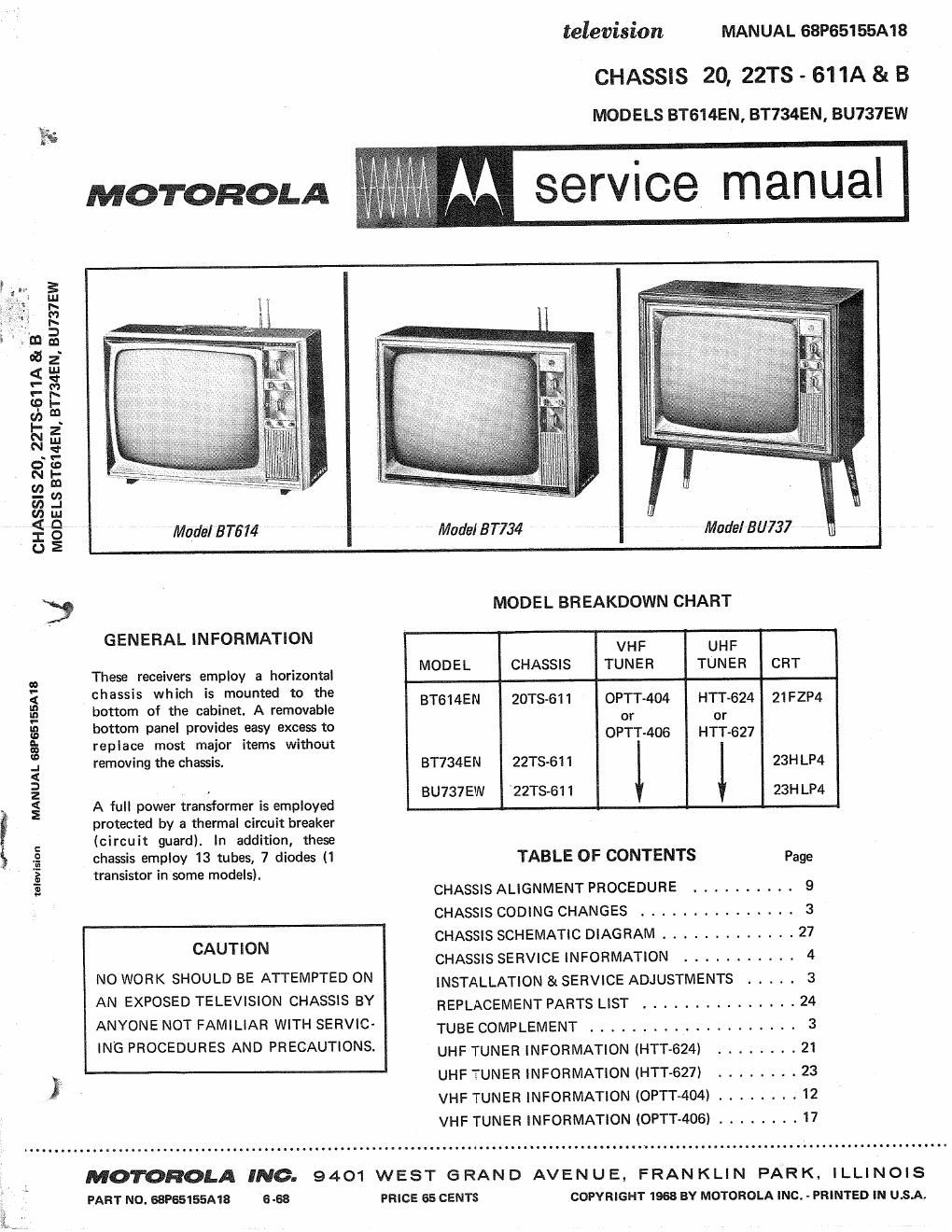
Motorola bt 734 en service manual

This is the 28 pages manual for motorola bt 734 en service manual.
Read or download the pdf for free. If you want to contribute, please mail your pdfs to info@audioservicemanuals.com.

Page: 1 / 28
left right
motorola bt 734 en service manual

Extracted text from motorola bt 734 en service manual (Ocr-read)


Page 1

television MANUAL 68P65155A18

CHASSIS 20, 22TS - 611A 8t B

MODELS BT614EN, BT734EN, BU737EW

mow-anon service manua

MadeiBTETJ " Modei 87734 ' ' Model'BUE? ~

MODELS BT614EN, BT734EN, BU737EW

CHASSIS 20, 22TS-611A 8L8. '

:3 MODEL BREAKDOWN CHART
GENERAL INFORMATION VHF UHF
n These receivers employ a horizontal MODEL CHASSB TUNER TUNER CRT
2 chassis which is mounted to the _ _ _
fl bottom of the cabinet A removable BT614EN 20TS 611 0P3: 404 H12; 624 21F2P4
3 bottom panel provides easy excess to _ _
g replace most major items without OPTT 406 HTT 627
i removing the chassis. BT734EN 22TS611 23H LP4
3 , BU737EW '22T3611 23HLP4
g A full power transformer is employed
protected by a thermal circuit breaker
= (circuit guard). In addition, these
i chassis employ 13 tubes, 7 diodes (1 TABLE OF CONTENTS Page
g transistor in some models).
8 CHASSIS ALIGNMENT PROCEDURE .......... 9
CHASSIS CODING CHANGES ............... 3
CHASSIS SCHEMATIC DIAGRAM ............. 27
CAUTION
CHASSIS SERVICE INFORMATION ........... 4
N0 WORK SHOULD BE ATTEMPTED 0 INSTALLATION & SERVICE ADJUSTMENTS ..... 3
AN EXPOSED TELEVS'ON CHASS'S BY REPLACEMENT PARTS LIST ............... 24
ANYONE NOT FAM'UAR W'TH SERV'C TUBE COMPLEMENT .................... 3
W6 PROCEDURES AND PRECAUTIONS UHF TUNER INFORMATION (HTT-624) ........ 21
it UHF TUNER INFORMATION (HTT-627) ........ 23
VHF TUNER INFORMATION (OPTT-404I ........ 12
VHF TUNER INFORMATION (OPTT-406) ........ 17

MOTOROLA INC. 9401 WEST e RAN D AVEN U E, FRAN KLI N PARK. ILLINOIS
PART NO. 68P65155A18 6-68 PRICE 65 CENTS COPYRIGHT 1968 BY MOTOROLA INC. - PRINTED IN U.S.A.

Page 2

SAFETY WARNING

CAUTION: NO WORK SHOULD BE ATTEMPTED ON AN EXPOSED TELEVISION CHASSIS BY ANY-
ONE NOT FAMILIAR WITH SERVICING PROCEDURES AND PRECAUTIONS.

l. SAFETY PROCEDURES should be developed
by habit so that when the technician is rushed
with repair work, he automatically takes pre-
cautions.


Z. A GOOD PRACTICE, when working on a re-
ceiver is to use only one hand when testing cir-
cuitry. This will avoid the possibility of care-
lessly putting one hand on chassis or ground and
the other on an electrical connection which could
cause a severe electrical shock.

3. Extreme care should be used in HANDLING
THE PICTURE TUBE as rough handling may
cause it to implode due to atmospheric pressure
_(l4.7lbs, per sq. 111.). Do not nick or scratch
glass or subject it to any undue pressure in re-
moval or installation. Whenhandling,use safety
goggles and heavy gloves for protection. Dis-
charge picture tube by shorting the anode con-
nection to chassis ground (not cabinet or other
mounting parts). When discharging . . . go from
ground to anode or use a well insulated piece of
Wire.

Avoid prolongedexposure at close range to un-
shielded areas of the cathode raytube. Possible
danger of personal injury from unnecessary ex-
posure to X- ray radiation may result.


4. A11 ISOLATION TRANSFORMER should al-
ways be used during the servicing of a receiver
whose chassis is common to one side of the
power line. Use a transformer of adequate
power rating as this protects the servicemen
from accidents resulting inpersonalinjuryfrom
electrical shocks. It will also protect the re-
ceiver and its components from being damaged
by accidental shorts of the circuitry that may
be inadvertently introduced during the service
operation,

5. Always REPLACE PROTECTIVE DEVICES,
such as fishpaper, isolation resistors and capac-
itors and shields after working on the receiver.

6. Do not operate the unit with the HIGH VOLT-
AGE COMPARTMENT OPEN or the cage re-
moved. The cover must be inplace and fastened
in order to assure proper shielding. This will
protect against the possibility of personal in-
jury resulting from unnecessary exposure to
X-ray radiation from the high voltage rectifier
tube.


15M WM 10 WA R£SI$TOR
msuumR \

Valtmeter Hook-up for Safety Check

7. The HIGH VOLTAGE should always be
ADJUSTED to the level recommended by the
manufacturer. If the voltage is increased above
the normal setting, exposure to unnecessary
X-ray radiation could result. High voltage can
accurately be measured with a high voltage
meter connected from the anode leadto chassis.

8. The TEST PICTURE TUBE used for ser-
vicing the chassis at the bench should incor-
porate a safety glass and magnetic shield. The
safety glass affords shielding for the tube
viewing area against X-ray radiation as well as
implosion protection. The magnetic shield
limits X-ray radiation around the bell of the
picture tube in addition to restricting magnetic
effects.

9. BEFORE RETURNING A SERVICED RE-
CEIVER (of any type) TO THE OWNER, the ser-
vice technician must thoroughly test the unit to
be certain that it is completely safe to operate
without danger of electrical shock. DO NOT
USE A LINE ISOLATION TRANSFORMER WHEN
MAKING THIS TEST.

In addition to practicing the basic and funda-

mental electrical saiety rules, the following

test, which is related to the minimum safety
requirements of the Underwriters Laboratories
should be performed by the service technician
before any receiver which has been serviced
is returned to the owner,

A 1000 ohm per Volt AC voltmeter is prepared
by shunting it with a 1500 ohm, lOwatt resistor.
The safety test is made by contacting one meter
probe to any portion of the receiver exposed to
the consmner or operator such as the cabinet
trim, hardware, controls, knobs, etc., while the
other probe is held in contact with a good
"earth" ground such as a cold water pipe.

The AC voltage indicated by the meter may not
exceed 7-1/2 volts, A reading exceeding 7-1/2
volts indicates that a potentially dangerous
leakage path exists between the exposed portion
of the receiver and "earth" ground. Such a re-
ceiver represents a potentially serious shock
hazard to the operator.

The above test should be repeated with the re-
ceiver power plug reversed.

NEVER RETURN A RECEIVER TO THE
CUSTOMER which does not pass the safety test
until the fault has been located and corrected.

yum WVDU 10R NIGER) AC VOLWETER

nuns: 1 REPEAT EACH cvscx mm m: Lmi cm sziksrn
__ m n: mm cum.

2 MUER READING MUSV NOYEXEIED 7-ll2 VOLTS AC.

"ROI" LEAD 0F MEYER TO EACH
EXPOSED PART 0? CAENCTU.
AS WELL AS Tl-E CARMEL

GROUND LEAD 0f METER TO ANV EARH
GROUND SUCH AS A COLD WATER PIPE\

a