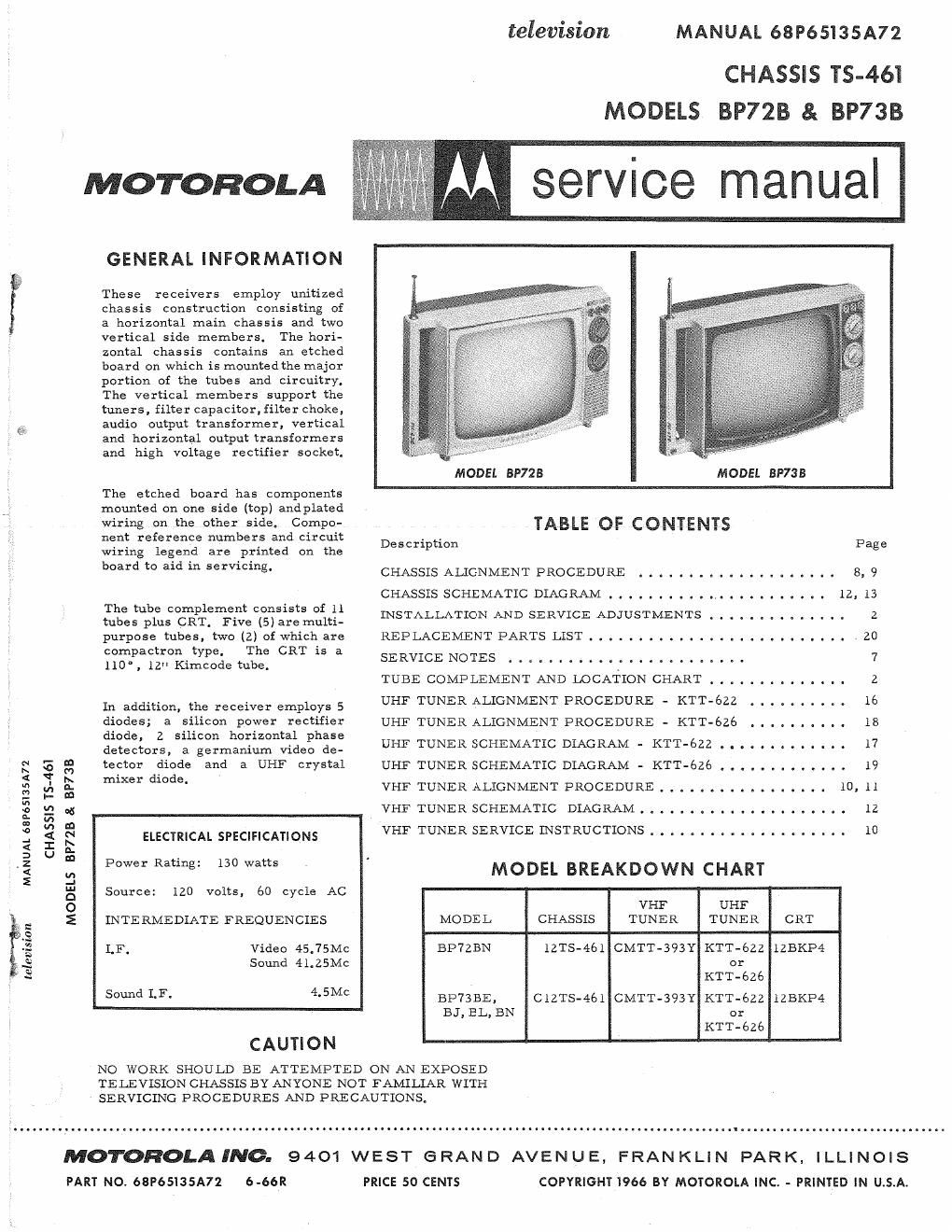
Motorola bp 72 b service manual

This is the 21 pages manual for motorola bp 72 b service manual.
Read or download the pdf for free. If you want to contribute, please mail your pdfs to info@audioservicemanuals.com.

Page: 1 / 21
left right
motorola bp 72 b service manual

Extracted text from motorola bp 72 b service manual (Ocr-read)


Page 1

television MANUAL 68P65135A72

CHASSIS TS-461
MODELS BP72B & BP73B

manualj

MOTOROLA


GENERAL INFORMATION

These receivers employ unitized
chassis construction consisting of
a horizontal main chassis and two
vertical side members. The hori-
zontal chassis contains an etched
board on which is mountedthe major
portion of the tubes and circuitry,
The vertical members support the
tuners, filter capacitor, filter choke,
@- audio output transformer, vertical
and horizontal output transformers
and high voltage rectifier socket.

MODEL BP723 MODEL BP7SB

The etched board has components

mounted on one side (top) andplated

wiring on the other sidee Compo- TABLE OF CQNIENTS

nent reference numbers and circuit Description Pa e
wiring legend are printed on the g

Imam m aid in servcmg' CHASSIS ALIGNMENT PROCEDURE . . . . . . . . . . . . . . . . . . . . 8, 9

CHASSISSCHEMATICDIAGRAM 12,13
The tube complement consists of II

tubes plus CRT Five (5) are multi- INSTALLATION AND SERVICE ADJUSTMENTS . . . . , . _ . . . _ . _ . 2
purpose tubes, two (2) of which are REPLACEMENT PARTS LIST . . . . . . . . . . . . . . . . . . . 20
compactron type, The CRT is a
llO',lleKimcodecube. SERVICENOTES 7
TUBE COMPLEMENT AND LOCATION CHART . . _ I . . . . . . . . . . 2
In addition the receiver employs 5 UHF TUNER ALIGNMENT PROCEDURE - KTT-ézz . . . . . . . . . ~ 16
.
diodes; a silicon power rectifier UHF TUNER ALIGNMENT PROCEDURE - KTT-626 . . . . . . . V . . 18
d d '1 h ' tal h
56:62;Srgermairifignvidei 2:? UHF TUNER SCHEMATIC DIAGRAM - KTT-bzz . . . . . . . . . . . . . 17
E g g: tector diode and a UHF crystal UHF TUNER SCHEMATIC DIAGRAM - KIT-626 I . r . . . . . . . . . e 19
< Ix ' d' d .
g i, g mxer 1° 9 VHF TUNER ALIGNMENT PROCEDURE . . . . . . . . . . l . . . . .. 10, 11
329; VHFTUNERSCHEMATIC DIAGRAM..................-.. 1-2
In
I V2 :1
2 E S ELECTRICAL SPECIFICATIONS VHF TUNER SERVICE INSTRUCTIONS . . . . . . . , . _ . , , . . , , , . 10
a U a
,z P Rati : 130 atts '
2 U, W ng W MODEL BREAKDOWN CHART
.-
3 Source: 120 volts, 60 cycle AC
0 VHF UHF
E INTERMEDIATE FREQUENCIES MODEL CHASSIS TUNER TUNER CRT
% LF. Video 45.75MC BP7ZBN lZTS-461 CMTT-393Y KTT-GZZ 125K134
3 Sound 41.25Mc or
3 KTT-626
50 1-3 4'5MC BP73BE, C12TS-461 CMTT-393Y KTT-622 lZBKP4
BJ, EL, EN or
KTT-626
CAUTION

NO WORK SHOULD BE ATTEMPTED ON AN EXPOSED
TELEVISION CHASSIS BY ANYONE NOT FAMILLAR WITH
SERVICING PROCEDURES AND PRECAUTIONS.

MOTOROLA INC. 9401 WEST e RAN D AVEN U E, FRAN KLIN PARK. ILLINOIS
PART NO. 68P65135A72 6-66R PRICE 50 CENTS COPYRIGHT I966 BY MOTOROLA INC. - PRINTED IN U.S.A.

Page 2

ONOFF FIL DROP V"

, SWITCH 33n- IOW MOUNTED X2
5 . ON TOP l T
E F RE\\ v12 CHASSIS H VOL
eKzs gem? *4
5 4v2 MIXER osc ,
-' J ELK
4 1
MIN: AMP
3HA5 0R 3HM5 m] vauomzos
VHF TUNER AUDIO IF gt g2); :1

PWEeR RECT LCF
UHF j.
; TUNER I
(TRANSISTOR , ..
INSIDE) 4BZ6 ""' / J N. 33GY7V gogjggg;
WSW rm" asset V B++ a
- _t>_CKGRouND GND 0 e

AC INTE RLO
CONNECT BLUE LEAD FROM PICTURE TUBE TO [AIR] 0R WHICHEVER PROVIDES BEST FOCUS

TUBE COMPLEMENT & LOCATION CHART

INSTALLATION AND SERVICE ADJUSTMENTS

FOCUSING ADJUSTMENT

To provide for differences in the
picture tube gun structure, a focus
adjustment is provided by three (3)
lugs located on the chassis. They
provide a ground potential point, a
13+ voltage point and a bootstrap
voltage point. Connect the blue lead
from the picture tube socket to the
lug which provides the best over-all
focus, center to edge of screen

FINE TUNING ADJUSTMENT

The low and high band of the VHF
tuner may be adjusted externally
from the front of the receiver (see
detail). The low band adjustment is
made with the channel #6 oscillator
adjustment screw located to the right
of the tuning shaft (see detail). The
high band adjustment is made with
the channel #13 oscillator adjust-
ment screw located to the left ofthe
tuning shaft,

Individual oscillator adjustments
are provided and are available with
the tuner removed from the tuner
mounting bracket. If individual os-

OS CILLATOR ADJUSTMENT

cillator adjustment is necessary, the
highest available channel should be
adjusted first and the remaining
available channels should be ad-
justed in descending order.

CHASSIS REMOVAL

Seven (7) screws secure the chassis
to the cabinet, They are located as
follows: Three (3) on the tuner
mounting bracket, one (1) at the
upper right hand corner and three
(3) on the bottom of the cabinet.

PICTURE TUBE REPLACEMENT

Use extreme care in handling the
picture tube as rough handling may
cause it to implode due to atmos-
pheric pressure. Do not nick or
scratch glass or subject it to any
undue pressure in removal or in-
stallation. Use goggles and heavy
gloves for protection.

To remove picture tube, remove
chassis as previously described,
then remove corner screws securing
picture tube to cabinet,