Motorola bp 307 d service manual

This is the 8 pages manual for motorola bp 307 d service manual.
Read or download the pdf for free. If you want to contribute, please mail your pdfs to info@audioservicemanuals.com.

Page: 1 / 8
left right
motorola bp 307 d service manual

Extracted text from motorola bp 307 d service manual (Ocr-read)


Page 1

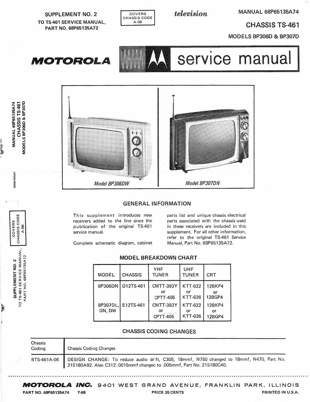
SUPPLEMENT N0. 2 COVERS television MANUAL 68P65135A74

CHASSIS cone
TO T8461 SERVICE MANUAL, AAOS

PART NO. 68P65135A72 CHASSIS TS-461
MODELS BP306D 81 BP307D

4M service manual

I

MOTOROLA

v \- D
h v.9 h
5 <5 3
e l2 s
3 :1) ea
9- :7: o
9.? cg g
" :I: 2
§ 0 m
z. 3
g m

D

O

E
E
E Made/BP306'DW MadelBPSWB/V

GENERAL INFORMATION
g This supplement introduces new parts list and unique chassis electrical
g 8 receivers added to the line since the parts associated with the chassis used
1;: :2 8 publication of the original TS~461 in these receivers are included in this
0 a < service manual. supplement. For all other information,
2 refer to the original TS-461 Service
0 Complete schematic diagram, cabinet Manual, Part No. 68P65135A72.
MODEL BREAKDOWN CHART
VHF UHF
MODEL CHASSIS TUNER TUNER CRT

BP3OBDN D12TS<461 CMTT-393Y KTT-622 128KP4
or or or
CPTT-405 KTT-626 IZBGP4
BP307DL, E12TS-461 CMTT-393Y KTT-622 123KP4
DN, DW or 77,, or or
CPTT-405 KTT-626 IZBGP4

SUPPLEMENT NO. 2
TO 73-461 SERVICE MANUAL,
PART NO 68P65135A72

CHASSIS CODING CHANGES

Chassis
Coding Chassis Coding Changes

BTS-46IA-O6 DESIGN CHANGE: To reduce audio drift, C305, IBmmf, N750 changed to 18mmf, N470, Part No
2IS180A92. Also C312 .0015mmf changed to .OOSmmf, Part No. 213180C40.

MOTOROLA INC. 9401 WEST GRAND AVENUE, FRANKLIN PARK, ILLINOIS

PART NO. 68P65135A74 7-68 PRICE 35 CENTS PRINTED IN USA.

Page 2

VHF ALIGNMENT PROCEDURE ~ CPU-405

Preliminary Steps

l. Before alignment is attempted,
make certain oscillator to mixer
grid injection voltage is adequate.
Connect VTVM to mixer T. 1:. ® .
See the tuners respective schematic
diagram for correct grid injection
voltage. If the mixer injection volt-
age is excessively high or low, cor-
rect by replacing mixer-oscillator
tube, if necessary. Checkthe tuners
B+, oscillator plate and grid voltage
and the components associated with
the oscillator portion of the mixer-
oscillator tube. Replace question-
able components.

2. If necessary, remove tuner from
bracket and re-position for better

accessibility. Secure in this posi~
tion. Make certain a good ground
is provided.

3. Connect a 1500 ohm, 60 wattvolt-
age normalizing resistor from 3+
to chassis if the horizontal is dis-
abled. To disable horizontal, un-
plug the two (2) yellow yoke leads.

4. Connect a variable bias supply to
tuner AGC line of feed-thru capaci-
tor on top of tuner, point Set
bias to -l.5 volts.

5. Do not remove tuner cover. Make
coil adjustment thru holes provided
in tuner shield.

6. Connect sweep generator, prop-
erly terminated to antenna input
terminals. See Figure 1 for sweep

gene rator termination network.

7. Maintain 0.5 volt peak-to-peak
output on scope.

8. Refer to "Tuner Alignment De-
tailH (Figure 2) for marker place-
ment on response curve.

9. For coil location, see the tuner's
respective component location de-
tail. See schematic diagramfor de-
tail of adjustment and Test Point
(T. P.) locations. '

10. If excessive hum is present on
scope. distorting the response curve
being viewed, connect an ade-uate
filter capacitor from B+ point to
chassis ground.

TUNER
CHANNEL
STEP SELECTOR GENERATOR INDICATOR ADJUST ADJUST FOR AND/OR REMARKS
1. Channel 13 Connect to antenna Connect scope L-14 and Place video marker (211.25Mc) on
terminal. Set gen- thru 47K re- L-Zl or near the peak of the response
erator for lOMc. sister to RF curve (see Figure 2).
Sweep width at T. P. ® (on
center of channel top of tuner) Place sound marker (215.75Mc) on
13 GZl3Mc). Set or near the peak of the response
marker generator curve (see Figure 2).
as required in last
column. See Fig - If bandwidth of response is too nar-
ure 1 for generator row or too wide, adjust by varying
termination. the high band coupling between the
RF plate and mixer grid wafers.
L-S (an- L.' excessive tilt is evident, adjust
tenna) for maximum amplitude and mini»
rnurntilt by spreading or compress-
ing coil with a non-metallic tool.
2. Channel 7 Same as Step #1 " Touchup Adjust for proper marker placement
except set genera- L-l4 and (175.25Mc Video tr 179.75Mc Sound).
tor to center ire- L-Zl, if (see Figure 2).
quency of channel neces-
7 (177Mc). Set Sary. NOTE; Repeat Steps 1 and 2 until
marker generator channels 7 and 13 response is within
as required in last specified limits. Channels 12 thru 8
column. will automatically fall within limits.
3. Channel 6 Same as Step #1 " EU? plate Antenna RF Plate Mixer
thru 2 except set genera- coil and Channel Coil Coil Coil
tor for correct mixer
center frequency coil. See 6 L>l3 L- 20 L»Z7
of the respective chart. 5 L- 12 L- 19 L- 26
channel. 4 L-ll L-l8 L-ZS
3 L- 10 L- 17 L- 24
See channel chart 2 L-9 L-lé L- 23
(Figure 3) for
correct frequency. Spread or compress the RF plate
and mixer coils of the respective
channels for proper marker place-
, o GEN. OUTPUT 31 32 ment of video and sound marker on
SWEEP l GENERATOR R'Z' ammo response curve 'asshown in Figure
81$:ka Eggmgém ANTENNA 50 50 125 Z. Kexcessive tilt is evxdent, adJust
TERMINALS (NORMALY IN PAD) R3 TERMINALS 75 75 115 the respective antenna cozl.
OAS-TM 150 150 75
15011 300 Garment to See Channel Chart (Figure 3) for
antenna terminal correct video and sound marker
frequencies of the respective chan-
Use the combination of resistors shown in table nels.

to match generator output impedance.

REA values.

Use nearest

FIGURE 1. GENERATOR MATCHING NETWORK FOR TUNER ALIGNMENT

2

rhea