Motorola af 7 smr service manual

This is the 12 pages manual for motorola af 7 smr service manual.
Read or download the pdf for free. If you want to contribute, please mail your pdfs to info@audioservicemanuals.com.

Page: 1 / 12
left right
motorola af 7 smr service manual

Extracted text from motorola af 7 smr service manual (Ocr-read)


Page 1

fm-am auto radio MANUAL 68P43IOIA04

AMERICAN MOTORS
MODEL AF7SMR

AMERICAN MOTORS

MODEL AF7SMR

MOTOROLA

GENERAL INFORMATION

Automotive type all-transistor
superheterodyne FM-AM radio; op-
erates from 12 volt negative ground
system. Designed for custom in-
stallation in the 1967 Rebel, Marlin
and Ambassador. This receiver
contains 2 plated chassis boards,
14 transistors and 6 diodes. Some
installations use a rear speaker and
control (AK-568) available at
American Motors dealers.

SERVICE STATION
PROCEDURE

1. A defective in-guarantee radio
must be accompanied by the Custom-
ers Guarantee Policy Tag. This tag
must be properly filled in. by the
American Motors dealer at the time
of radio purchase, Accept as guar:
antee repairs only those radios with-
in the 2 years or 24,000 miles
(whichever occurs first] guarantee
period, The removal or re-install-
ation of this receiver is customarily
performed by the American Motors
dealer and is not covered by this
guarantee. Also, the removal of
motor noise, tire static, electrical
interference, faulty installations and
aerial repairs are not considered
as guarantee repairs and,there£ore,
expenses related to such services
should be handled by the car dealer.

2. Fill in MotorolaC-uarantee Labor
Claim, Part Number 68P60016A30
and 'r'nail Green and Pink copies to:

Motorola Guarantee Service V
Motorola Automotive Products, Inc.
940 1 West Grand Avenue

Franklin Park, Illinois.

3. The yellow copy of the Motorola
Guarantee Labor Claim is to be re-
tained by the authorized service
station for his files.

4. Defective parts for guarantee re-
pairs made on this model are to be
send toiyour Motorola Distributor
for free replacement supportedwith
the defective parts return tag or
form which you are now using,

5. Only those service shops author-

4- I

ized by their Motorola Distributor
can perform guarantee repairs on a
no-charge basis to the customer. If
you are not already authorized as a
Motorola Auto Radio Service Station
and you are interested in handling
this service, please contact your
Motorola Distributor for complete
details. '

TO SET PUSHBUTTONS

Each pushbutton can be set to one
station only - either an AM or an
FM station. Thus, a total of 5
stations can be selected. These five
stations can be five AM stations, five
FM stations, or any combination of
five AM and FM stations.

Set, pushbuttons as follows:

1. Turn radio on and allow to oper-
ate for fifteen minutes.

2. Adjust antenna to height of 36
inches (recommended for best FM
reception),

3. Position band switch to AM or
FM.

4. Pull out top pushbutton to its stop
(approximately 3/8 inch).

5. Tune in desired station.

6. Lock the pushbuttonto this station
by pushing in button approximately
3/4 inch (fully in).

7, Repeat Steps #3, #4, #5 and #6
to set each of the remaining push-
buttons (be sure to observe Step #3
for each pushbutton),

SERVICE NOTES

1. RADIO POLARITY - WHEN SER-
VICING THIS RECEIVER, THE A"
LEAD MUST BE CONNECTED TO
THE POSITIVE SIDE OF POWER
SOURCE. IF CONNECTEDO-THER-
WISE, RECEIVER WILL NOT OP-
ERATE AND DAMAGE TO COM-
PONENTS MAY RESULT.

2. POWER SUPPLY REQUIRE-
MENTS - It is preferable to use a
storage battery (without a battery

charger) in place of a battery slim»
inator. If a battery eliminator is
used, it must be well filtered and
regulated.

3. PLATED CHASSIS BOARD DE-
SCRIPTION » Motorolas PLAcir
chassis has plating on both sides of
the chassis board. Leads are plated
on both sides of the chassis base
and the plating extends through the
holes on the chassis, connecting
circuits on the top with those on the
bottom. B- connections are carried
through the PLAcir chassis in mul-
tiple paths to insure a good low
resistance return path.

4. TO SERVICE PLATED CHASSIS
- To remove the plated chassis
from the radio housing,unsolder the
ground leads connected to the plated
chassis mounting bracket,
Straighten the ears on the chassis
mounting bracket, then unsolder and
remove the bracket. Unsolder
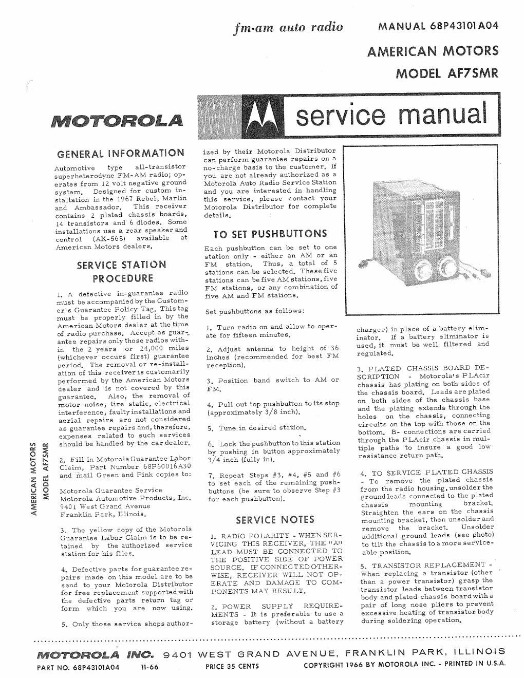
additional ground leads (see photo)
to tilt the chassis to amore servicev
able position,

5. TRANSXSTOR REPLACEMENT -
When replacing a transistor (other
than a power transistor) grasp the
transistor leads between transistor
body and plated chassis boardwitha
pair of long nose pliers to prevent
excessive heating of. transistor body
during soldering operation.

MOTOROLA INC. 9401 WEST GRAND AVENUE, FRANKLIN PARK, ILLINOIS

PART NO. 68P4310IA04

-66

PRICE 35 CENTS

COPYRIGHT 1966 BY MOTOROLA INC. - PRINTED IN U.S.A.

Page 2

6. POWER TRANSISTOR RE- in the Replacement Parts List. to insureproperheatdissipation.
PLACEMENT - When replacing a

power transistor, be sure to: B. Coat both sides of transistor (2 Securely and evenly tighten
insulator with DC-4 grease the transistor mounting screws.
A. Use the transistor specified (Motorola Part No. 11M490487)

PLNED
CHASSIS
MOUNHNG
BRACMfi

'*~GROUND
LEADS

,2 PARTS LOCATION

an x. W