Motorola 240 service manual

This is the 8 pages manual for motorola 240 service manual.
Read or download the pdf for free. If you want to contribute, please mail your pdfs to info@audioservicemanuals.com.

Page: 1 / 8
left right
motorola 240 service manual

Extracted text from motorola 240 service manual (Ocr-read)


Page 1

raw.

MANUAL 68P43100A87

MODELS 237, 240

MOTOROLA INC.
PART No. 68P43100A87

MOTOROLA

GENERAL INFORMATION

All-transistor AM radios which op-
erate froma 12 volt negative ground
system. These radios are designed
for custom installation in the follow-
ing cars:

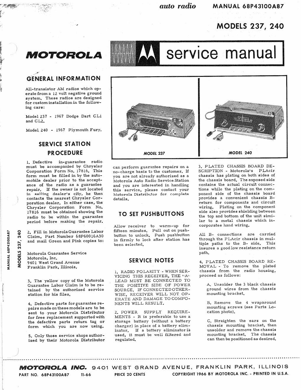
Model 237 - 1967 Dodge Dart CLl
and CLZ.

Model 240 - 1967 Plymouth Fury.

SERVICE STATION
PROCEDURE

1. Defective in-guarantee radio
must be accompanied by Chrysler
Corporation Form No. 17816. This
form must be filled in by the auto-
mobile dealer prior to the accept-
ance of the radio as a guarantee
repair. If the owner is not located
in selling dealers city, he then
contacts the nearest Chrysler Cor-
poration dealer. In either case, the
Chrysler Corporation Form No.
17816 must be obtained showing the
radio to be within the guarantee
period before making the repair.

2. Fill in MotorolaGuarantee Labor
Claim, Part Number 68P60016A30
and mail Green and Pink copies to:

Motorola Guarantee Service
Motorola, Inc.

9401 West Grand Avenue
Franklin Park, Illinois.

3. The yellow copy of the Motorola
Guarantee Labor Claim is to be re-
tained by the authorized service
station {or his files.

4. Defective parts forguarantee re-
pairs made on these models are to be
sent to your Motorola Distributor
for free replacement supportedwith
the defective parts return tag or
form which you are now using.

5. Only those service shops author-
ized by their Motorola Distributor

-66

auto radio

service manual

MANUAL 68P43IOOA87

MODELS 237, 240

MODEL 237

MODEL 240

can perform guarantee repairs on a
no- charge basis to the customer. If
you are not already authorized as a
Motorola Auto Radio Service Station
and you are interested in handling
this service, please contact your
Motorola Distributor for complete
details.

TO SET PUSHBUTTONS

Allow receiver to warm-up for
fifteen minutes. Pull out on push-
button to unlock. Push pushbutton
in firmly to lock after station has
been selected.

SERVICE NOTES

1. RADIO POLARITY - WHEN SER-
VICING THIS RECEIVER, THE "A
LEAD MUST BE CONNECTED TO
THE POSITIVE SIDE OF POWER
SOURCE. IF CONNECTEDOTHER-
WISE, RECEIVER WILL NOT OP-
ERATE AND DAMAGE TO COMPO-
NENTS WILL RESULT.

2. POWER SUPPLY REQUIRE-
MENTS - It is preferable to use a
storage battery (without a battery
charger) in place of a battery elim-
inator. If a battery eliminator is
used, it must be well filtered and
regulated.

PRICE 20 CENTS

3. PLATED CHASSIS BOARD DE-
SCRIPTION - Motorolas PLAcir
chassis has plating on both sides of
the chassis board. The exposed side
contains the actual circuit connec-
tions while the plating on the com-
ponent side of the chassis board
provides a convenient chassis B-
return for components and circuit
wiring. Plating on the component
side also provides shielding between
the top and bottom of the unit simi-
lar to a metal chassis which in-
corporates hand wiring.

All 3- connections are carried
through the PLAcir chassis in mul-
tiple paths to the B- side, This
insures a good low resistance return
path.

4. PLATED CHASSIS BOARD RE~
MOVAL - To remove the, plated
chassis from the radio housing,
proceed as follows:

A. Unsolder the 3 black chassis
ground Wires from the chassis
mounting bracket.

B, Remove the 4 wraparound
mounting screws (see Parts Lo-
cation photo).

C. Straighten the ears on the
chassis mounting bracket, then
unsolder and remove the chassis
mounting bracket. The chassis
can then be positioned as desired.

9401 WEST GRAND AVENUE, FRANKLIN PARK, ILLINOIS
COPYRIGHT I966 BY MOTOROLA INC. - PRINTED IN U.S.A,

Page 2

5. TRANSISTOR REPLACEMENT -
When replacing a transistor (other
than a power transistor), grasp the
transistor leads (betweentransistor
body and plated chas: board) with
a pair of long nose pliers to prevent
excessive heating of transistor body
during soldering operation.

6, POWER TRANSISTOR RE-
PLACEMENT - When replacing a
power transistor, be sure to:

A. Use the transistor specified
in the Replacement Parts List.

Connect an output meter acres the speaker voice coil, Set volume to maximum and tone to high.

B. Coat 'hoth sides of transistor
insulator with DC-4 grease
(Motorola Part No. 11M490487)
to insure proper heat dissipation.

C. Securely and evenly tighten
the transistor mounting screws.

TRANSISTOR RECEIVER
SERVICE METHODS

Trouble shooting transistor radios
is basically similar to servicing
tube sets. First, isolate the defec-

ALIGNMENT

tive stage through signal injection;
next, through the use of Voltage and
resistance measurements, plus
Motorola's servicing tools, deter-
mine the necessary maintenance
required. Motorola's servicing
methods and aids, when properly
used, can help make transistor ler-
vice easier.

Refer to "Profitable Transistor
Radio Servicing" manual (Motorola
Part No. 68P60011A53) and "A Dis-
cussion Of Transistorized Car
RadiosH manual (Motorola Part No.
68Pé49 SOAS l).

Attenuate

signal generator output to maintain 2.8volts on output meter at all times to prevent overloading the receiver .

GENERATOR
GENERATOR FREQUENCY
STEP CONNECTION (400 cycle mod) TUNER SET TO ADJUST REMARKS
IF ALIGNMENT
l. Antenna receptacle 262.5Kc High end stop 1, 2. 3 8: Adjust for maximum.
thru . lmf capacitor
and ground.
RF ALIGNMENT
2. Antenna receptacle lblOKc High end stop 5, 6 8: 7 Adjust for maadmum.

thru dummy antenna
(see Figure).

NOTE: Do not perform Steps

been replaced. Before proceeding with Step 3,back

trimmer adjustments. Remove

3. Antenna receptacle
thru dummy antenna
(see Figure).

4. n

6. Repeat Steps 4 and 5
step.

\

ANTENNA T RIMME R

7. --

__. Weak station
around 1400K:

3, 4, 5 and 6 unless the tuner has been tampered with or components have
tuning cores out of coils to eliminate their effect on the
dial scale and background to expose core screws.

1&ch High end stop 5, 6 & 7 Adjust for maximum.
lOZOKc Tuner carriage 8, 9 £110 Adjust for maximum.
9/16" from
high end stop
lélOKc High and stop 5, 6 81 7 Adjust for maximum.

until no further increase, then cement cores in place. Step 5 should be last

' With radio installed in car
and antenna fully extended,
peak antenna trimmer for
maximum.

PLUG TO FIT RECEIVER

_._..___ ANTENNA RECEPTACLE
I" I
TO SIGNAL -...I 4 PF T0 RECEIVER
GENERATOR« °-1» --. ~>ANIENNA
I RECEPTACLE
I I METAL SHIELD CAN
l.___ __ _.l musr a: ATTACHED
TO PLUG

DUMMY ANTENNA