Page 1
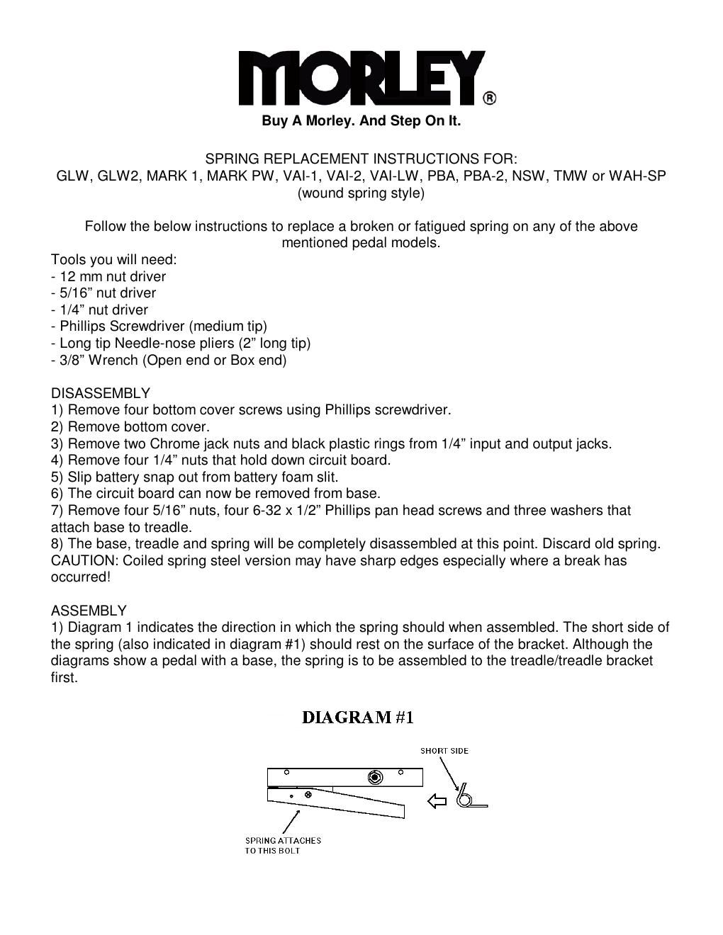
2) Diagram #2 shows the proper assembly order of spring and associated components.
3) Place all components (per diagram #2) into place.
4) Place base onto treadle and align screw hole opening s in base to line up with holes in treadle
bracket.
5) Place a int. tooth washer on 6-32 a 1/2 screw. Using the needle-nose pliers, hold the 6-32 x
1/2 Phillips pan head screw by the head and insert from underside of treadle bracket. (The thread
should stick up in the inside of the pedal base) Replace w asher and 5/16 nut. Repeat for three
remaining mounting locations. Do not tighten any of th e four nuts yet.
6) Align and center treadle to base. This can be accompli shed by setting the pedal assembly on
its heel end to push treadle as far toward the toe end as possible and visually centering the
treadle (so it is not cocked right or left). This is impor tant so the shutter is located properly
between the optics.
7) Tighten the four 5/16 nuts thoroughly.
8) Set the screw tightness on each side of the treadle. T o accomplish this, place the 3/8 wrench
on the nut located on the inside of the treadle/bracket assembly. Tighten bolt all the way down
and loosen it one half turn to allow treadle to move freely. Repeat for opposite side.
9) Replace circuit board, four 1/4 nuts, two black plasti c rings & two chrome jack nuts.
10) Insert battery snap through the slit in battery foam .
11) Perform sound test to verify wah setting is still with in acceptable range.
12) Replace bottom cover and bottom cover screws.
13) Diagram #3 shows the assembled spring.
If you need further assistance, please contact Scot t Flesher
at 1-800-284-5172 ext 15 or scott@morleypedals.com