Moog voyager notice document

This is the 32 pages manual for moog voyager notice document.
Read or download the pdf for free. If you want to contribute, please mail your pdfs to info@audioservicemanuals.com.

Page: 1 / 32
left right
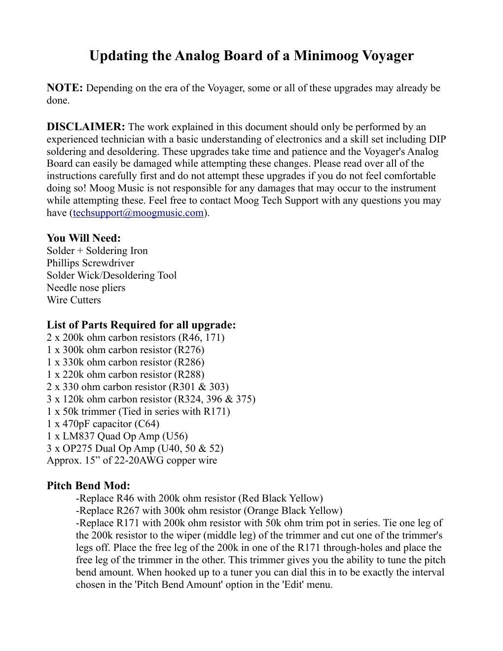
moog voyager notice document

Extracted text from moog voyager notice document (Ocr-read)


Page 1

Waveshaping Mod: -Replace R324, 396 & 375 with 120k ohm resistor (Brown Red Yellow) Signal to Noise Ratio Increase: -Replace U56 with LM837 Quad Operational Amplifier IC -Replace U40, 50 & 52 with OP275 Dual Operational Amplifier -Add 470pF capacitor in the non-populated spot for C64 (wedged between R335 &336). NOTE: If C64 is not installed in tandem with the OP275's the Voyager will not function properly. LFO Mod: -Replace R286 with 330k ohm resistor (Orange Orange Yellow) -Replace R288 with 220k ohm resistor (Red Red Yellow) Headphone Output Mod: -Replace R301 & 303 with 330 ohm resistor (Orange Orange Brown) NOTE: The headphone output is the most important modification for the stability of the analog board.

Page 2

Filter Glide Mod: -Lift the bottom leg of R133 and jump (via approx. 3 of wire) to the top leg of R43. R43 remains connected to the circuit. Remember to move the lifted leg of R133 off to the side to make sure that there is no way it could short to any neighboring component. It is a good idea to use the added support of Silicon or some other non-conductive translucent adhesive.