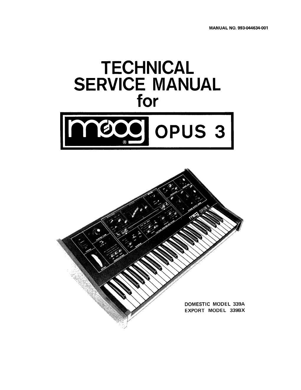
Moog opus 3 service manual

This is the 43 pages manual for moog opus 3 service manual.
Read or download the pdf for free. If you want to contribute, please mail your pdfs to info@audioservicemanuals.com.

Page: 1 / 43
left right
moog opus 3 service manual

Extracted text from moog opus 3 service manual (Ocr-read)


Page 1

MANUAL NO. 993-044634-001

TECHNICAL
SERVICE MANUAL
or

OPUS 3

DOMESTIC MODEL 339A
EXPORT MODEL 33QBX

Page 2

ii

SECTION
1

FIGURE

3-1
3-2

3-3
4-1
4-2
4-3
6-1
6-2
6-3
6-4
65
6-6
6-7

CONTENTS

INTRODUCTION AND SPECIFICATIONS ......................
1.1 GENERAL ..............................................
1.2 SPECIFICATIONS ........................................

CIRCUIT DESCRIPTION ....................................
2.1 KEYER/POWER SUPPLY BOARD l ............................
2.2 CONTROL BOARD 2 ......................................
2.3 CHORUS MODULATION BOARD 3 ............................

DISASSEMBLY AND REASSEMBLY ..........................
3.1 REMOVAL PROCEDURES ..................................
3.2 REASSEMBLY ..........................................

FIELD TEST PROCEDURE AND TROUBLESHOOTING ............
4.1 FIELD TEST PROCEDURE ..................................
4.2 ABBREVIATED TROUBLESHOOTING ..........................

REPLACEMENT PARTS LIST ................................

SCHEMATIC DIAGRAMS AND PRINTED CIRCUIT BOARDS ......

LIST OF ILLUSTRATIONS

Removal of Base ............................................
Opus 3 with Base Removed, Keyer/Power Supply and Chorus Modulator
Printed Circuit Boards Removed and Control Printed Circuit Board
Installed ................................................
Keyboard ..................................................
Initial Setup ................................................
Articulation Mode 1 ........................................
Articulation Mode 2 ........................................
Functional Block Diagram ....................................
Keyer/Power Supply Printed Circuit Board Diagram ................
Keyer/Power Supply Schematic Diagram ..........................
Control Printed Circuit Board Diagram ..........................
Control Schematic Diagram ....................................
Chorus Modulator Printed Circuit Board Diagram ..................
Chorus Modulator Schematic Diagram ............................
Sample Sound Charts

These drawings and specifications are the property of Moog Music Inc., and shall not be
reproduced or copied in whole or in part as the basis for manu'acture or sale of the items.

PAGE NO.
1-1
1-1
1-1

1-2/2-0

1»2/2-0
2-2
2-6

2-7/3-1

2-7/3-1
3-2
4-0
4-0
4-3
5-0

5-7/6-1

PAGE NO.
2-7/3-1