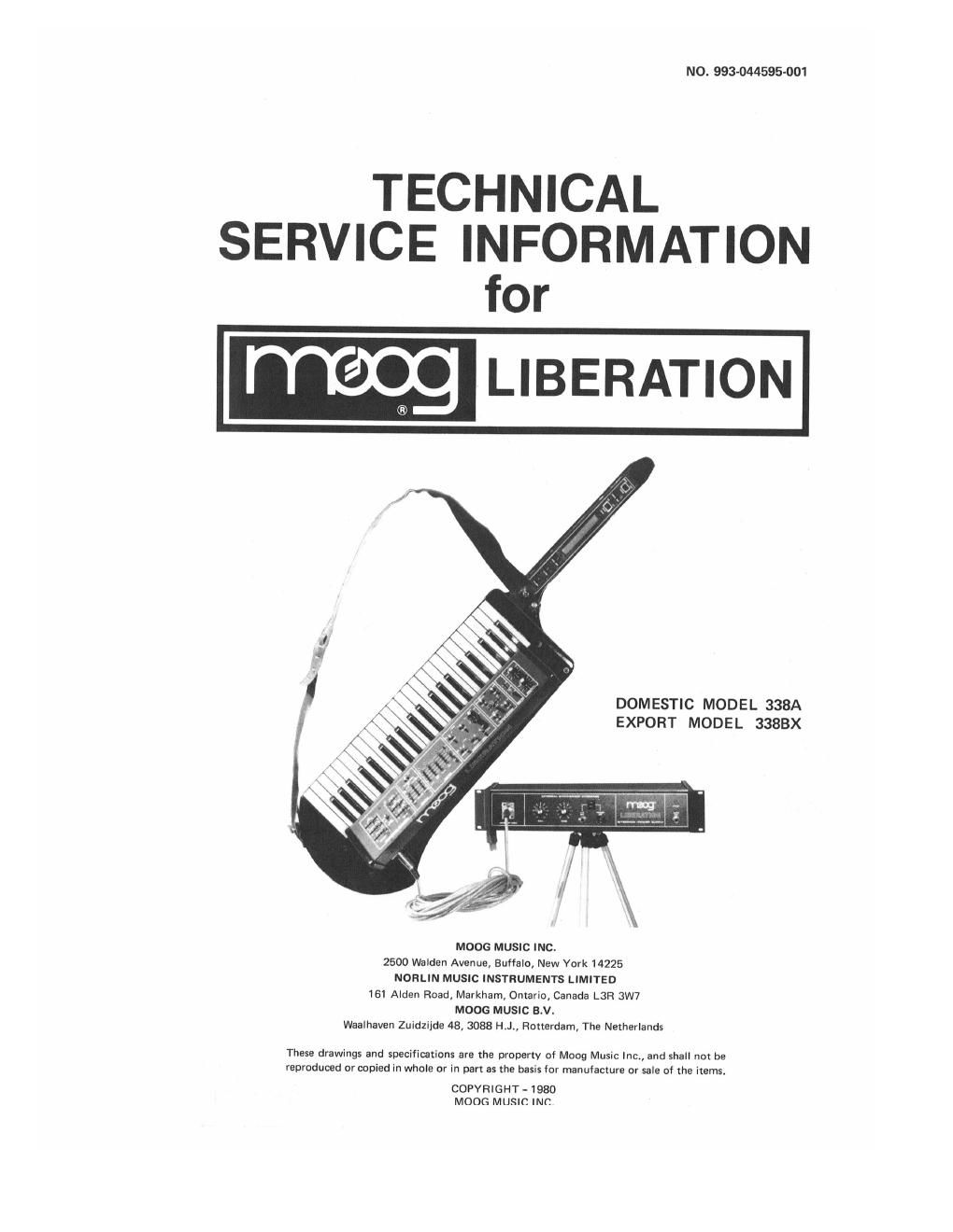
Moog liberation service manual

This is the 13 pages manual for moog liberation service manual.
Read or download the pdf for free. If you want to contribute, please mail your pdfs to info@audioservicemanuals.com.

Page: 1 / 13
left right
moog liberation service manual

Extracted text from moog liberation service manual (Ocr-read)


Page 1

N0, 993-044595-001

TECHNICAL
SERVICE INFORMATION
for

LIBERATION


DOMESTIC MODEL 338A
EXPORT MODEL 3388X

MOOG MUSIC INC.
2500 Walden Avenue, Buffalo, New York 14225
NORLIN MUSIC INSTRUMENTS LIMITED
161 Alden Road, Markham, Omariu, Canada L3H 3W7
MOOG MUSIC B.V.
Waalhaven Zuidzijde 48, 3088 H.J., Rotterdam, The Nesherlands

These drawings and specifications are the properly of Moog Music Inc., and shall not be
reproduced or copied in whole or in part as the basis for manufacture or sale of the iKems.

COPVFIIGHT- 1980
MOOG MUSIC INC

Page 2

DISASSEMBLV PROCEDURES

CAUTION
Before proceding with disassembly, take special care to protect the
finished wooden portions of the instrument from damage from
sharp objects. The use of carpeting or Styrofoam is recommended.

KEYBOARD CIRCUIT

1. To gain access to the keyboard circuit, remove the bottom cover by re-
moving the eight screws and cup washers. This will provide the capability
to troubleshoot the oscillator, the keyboard circuit, 12 volt regulator,
VCA, VCF, force sensor and circuitry associated with the left-hand
controller.

N

. The board may be completely loosened by removing the {our screws and
lock washers along the center of the printed circuit board and connectors
$19, $110, $111 and $113. This yields access to the keyboard contacts.

3, The force sensor may be removed by loosening the printed circuit board
and removing the two mounting screws of the opto-interrupter at the
center of the keyboard

CONTROL BOARD

1.The control board assembly may be disassembled by removing the two
10-32 3/4" screws and washers at each end of the top assembly. To
completely remove the printed circuit board, remove knobs from controls
and sliders. the three screws on the back and the {our screws securing the
printed circuit board in place.

LEFT-HAND CONTROLLER

1. To gain access to the switches and controls, remove only the two screws
at each end of the neck.

POWER SUPPLY/l NTER FACE

1. To gain access to the power supply, remove the three screws on the rear lip
of the back panel chassis, three screws on the top extmsicn and the two
top screws from each end cap. This allows the top cover to be removed.

OVERALL TROUBLESHOOTING

1. After the instrument is fully dismembled it is suggested that the instru-
ment neck be strongly supported with a suitable material such as foam to
facilitate troubleshooting. The loam can be used quite successfully by
cutting an under-sized rectangular hole in the foam at a height that places
the instrument in a horizontal plane with the keyboard facing up.

STVROFoAM

OPTo-I NTE R RUPTER


PRINTED CIRCUIT
BOARD MOUNTING
SCREWS AND
WASHERS (GI

KEVEOARD PRINTED

BOTTOM COVER CIRCUIT BOARD

scR laws AND

CUPWASHERS IN PLACE
aoTToM
covE R

POWER SUPPLY/INTERFACE

POWER SUPPLV
PRINTEDCIRCUIT BOARD

CONTROL PRINTED
CIRCUIT BOARD
REMOVED

TOP ASSEMBLY

SLIDE CONTROL
DusT SHIELD

SLIDE CDNTROL
DUST SHIELD

TOP ASSEMBLY
" son ews

6 (2)
PRINTED cIRcUIT 1D,, ASSEMBL-V m a - CONTROL Kuoas
BOARD GUIDE BACK SCREWS -
SLIDER KNom

LEFT-HAND
NECK CONTROLLER

SCREWS (4)