Mitsubishi m t01 service en

This is the 19 pages manual for mitsubishi m t01 service en.
Read or download the pdf for free. If you want to contribute, please mail your pdfs to info@audioservicemanuals.com.

Page: 1 / 19
left right
mitsubishi m t01 service en

Extracted text from mitsubishi m t01 service en (Ocr-read)


Page 1

A MITSUBISHI

AUDIO SYSTEMS

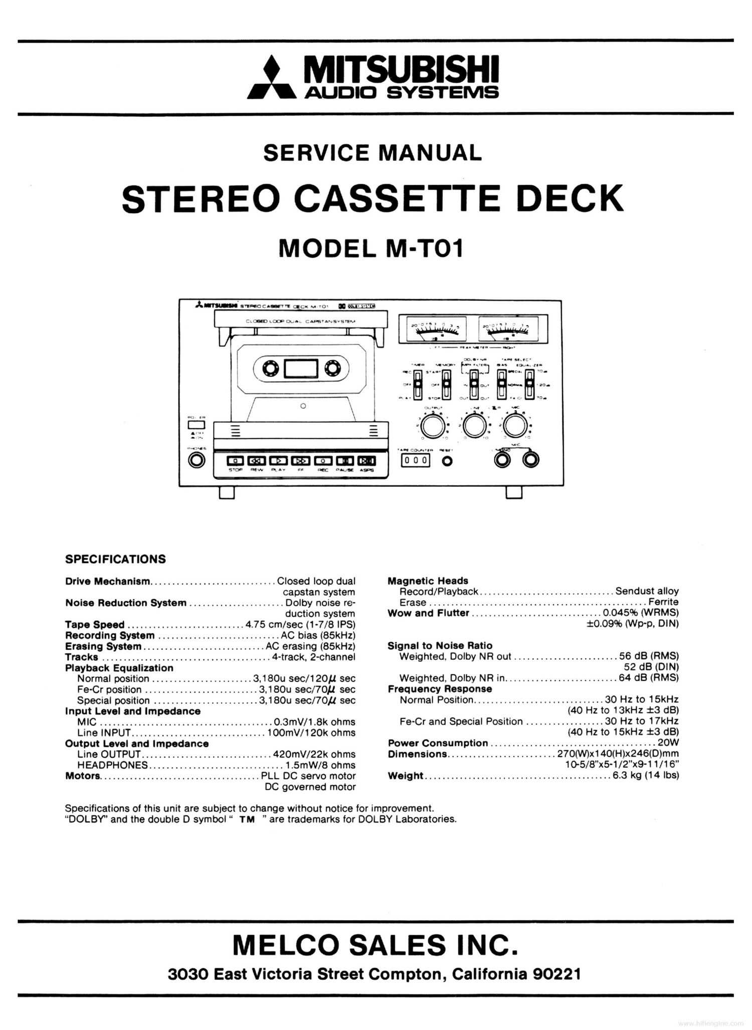
SERVICE MANUAL

STEREO CASSETTE DECK
MODEL M-TO1

SPECIFICATIONS
Drive Mechanism ............................. Closed loop dual
capstan system
Noise Reduction System ...................... Dolby noise re-
duction system

Tape Speed ........................... 4.75 cm/sec (1-7/8 IPS)
Recording System ............................ AC bias (85kHz)
Erasing System ............................ AC erasing (85kHz)
Tracks ....................................... 4-track. 2-channel
Playback Equalization

Normal position ....................... 3,180u sec/120p sec

Fe-Cr position .......................... 3,180u sec/70p sec

Special position ........................ 3,180u sec/70y sec
input Level and impedance

MIC ........................................ O.3mV/1.8k ohms

Line INPUT ............................... IOOmV/t 20k ohms
Output Level and Impedance

Line OUTPUT .............................. 420mV/22k ohms

HEADPHONES ............................... 1.5mW/8 ohms
Motors ..................................... PLL DC servo motor

DC governed motor

Magnetic Heads

Record/Playback ............................... Sendust alloy
Erase .................................................. Ferrite
Wow and Flutter .............................. 0.045% (WRMS)

$00996 (Wp-p, DIN)

Signal to Noise Ratio

Weighted. Dolby NR out ........................ 56 dB (RMS)

52 dB (DIN)

Weighted. Dolby NR in .......................... 64 dB (PMS)
Frequency Response

Normal Position .............................. 30 Hz to 15kHz

(40 Hz to 13kHz :3 dB)

Fe-Cr and Special Position .................. 30 Hz to 17kHz

(40 Hz to 15kHz :3 dB)

Power Consumption ...................................... 20W

Dimensions ......................... 270(W)x140(H)x246(D)mm

10-5/8"x5-1/2"x9-1 1/16"

Weight ........................................... 6.3 kg (14 lbs)

Specifications of this unit are subject to change without notice for improvement.
DOLBY and the double D symbol TM are trademarks for DOLBY Laboratories.

MELCO SALES INC.

3030 East Victoria Street Compton, California 90221

Page 2

FRONT PANEL TERMINOLOGY AND FUNCTIONS

@Powen (Power switch)

DUST COVER
en not in use, close this cover to protect the
magnetic heads and mechanical parts from dust.

©PHONES (Headphone jack)
Be sure to use headphones with an impedance of
more than 8 ohms.

@STOP (I Stop button)
Press this button to stop the tape.

@nEw ( « Rewinding button)
By pressing this button, the tape rewinds at high
speed.

.PLAY( 1 Playback button)
Press this button for playback or recording.

@FF ( b) Fast-forward winding button)
By pressing this button, the tape advances at
high speed.

.REC ( 0 Recording button)

For recording pressthe PLAYbutton while press-
ing this button When the cassette is not loaded
or eithertab in the rear of the cassette is removed,
the failsafe-recording mechanism works and re-
cording will not proceed.

0 PAUSE ( II Pause button)

'ress this button to temporarily stop the tape
during recording or playback. By pressing this
button once again, the pause mechanism is re-
leased and recording or playback will resume.

® ASPS. (>"Automatic spacing pause
button)

ASPS is the Automatic Spacing Pause System.

By pressing this button during recording, input

signals will be muted for about 3 seconds and

after that, the pause mechanism will automati-

cally function. Please see page 9 for details.

TAPE COUNTER and RESET BUTTON
the start of recording, push the reset button to
set the tape counter to 000". If you list the
recorded programs and the indexing figures of
the tape counter, you can easily cue a program
for playback.

OUTPUT (Output level control)
is control is for adjusting the levels of the
output signals through the OUTPUT terminals on
the rear panel and also through the PHONES
jack.

LINE (Line Input level control)
ese controls are for adjusting the levels of the
recorded signals through the lNPUTterminals on
the rear panel.

MIC (Microphone input level control)
ese controls are for adjusting the levels of the
recorded signals through the microphone Inputs.

MIC (Microphone jacks)
or monaural recordings of both the right (R) and
left (L) channels, insert the microphone plug into
the L channel input.

®® (D
I

AM era-coconut"! got u st ' m

C L m.L c 'msvs NEE
. :v a. I v

OOO

OOOOOOID O ®®® <9

TAPE SELECT. BIAS and EOUALIZER

electthe optimum bias current in recording and
the equalizer characteristics in recording and
playback according to the tape used. See page 7
for positioning of these switches.

@ DOLBY NR/MPX FILTER (Dolby noise

reduction and multiplex filter switch)
Set this switch to the DOLBY NR W" and MPX
FILTER OUT" position for Dolby recording. In
this case, be sure to set this switch to the DOLBY
NR IN and MPX FILTER OUT" position during
playback; Similarly, when you record with this
switch set to the DOLBY NR OUT" position, play
the tape with the same switch setting. The posi-
tion of the DOLBY NR IN and MPX FILTER IN"
is only for recording from FM stereo broad-
casting.

® MEMORY (Memory switch)

. the start of recording or playback, set the tape
counter to 000" by pushing the reset button,
then set this switch to the STOP or START posi-
tion. When you rewind the tape after recording or
playback, the tape automatically stops its run-
ning or restart to playback at the "999 of the tape
counter.

9 TIMER (Timer switch)

sing the commercial timer. you can automati-
cally record or playback at the pre-set time. See
page 10 for details.

PEAK METERS
ese meters indicate the peak levels of the in-
put signals during recording as well as the record-
ed signals during playback. The output level
control has no effect on the needle movements of
the peak meters.

POSITIONING OF TAPE SELECT SWITCHES.
Select the positions of TAPE SELECT switches
(BIAS and EQUALIZER switches) as follows. If
you cannot find out your tape in the table, please
refer to the instructions of the tape forthe correct
positioning.

Position of

Bias It Equal-
MID. .... 9......

Fsanocuaou -

CRYSTAL

SCOTCH MASTER

CLASSIC -

LH
SUPER

LN
SONY HF

RANGE 2
RANGE 4

MAXELL