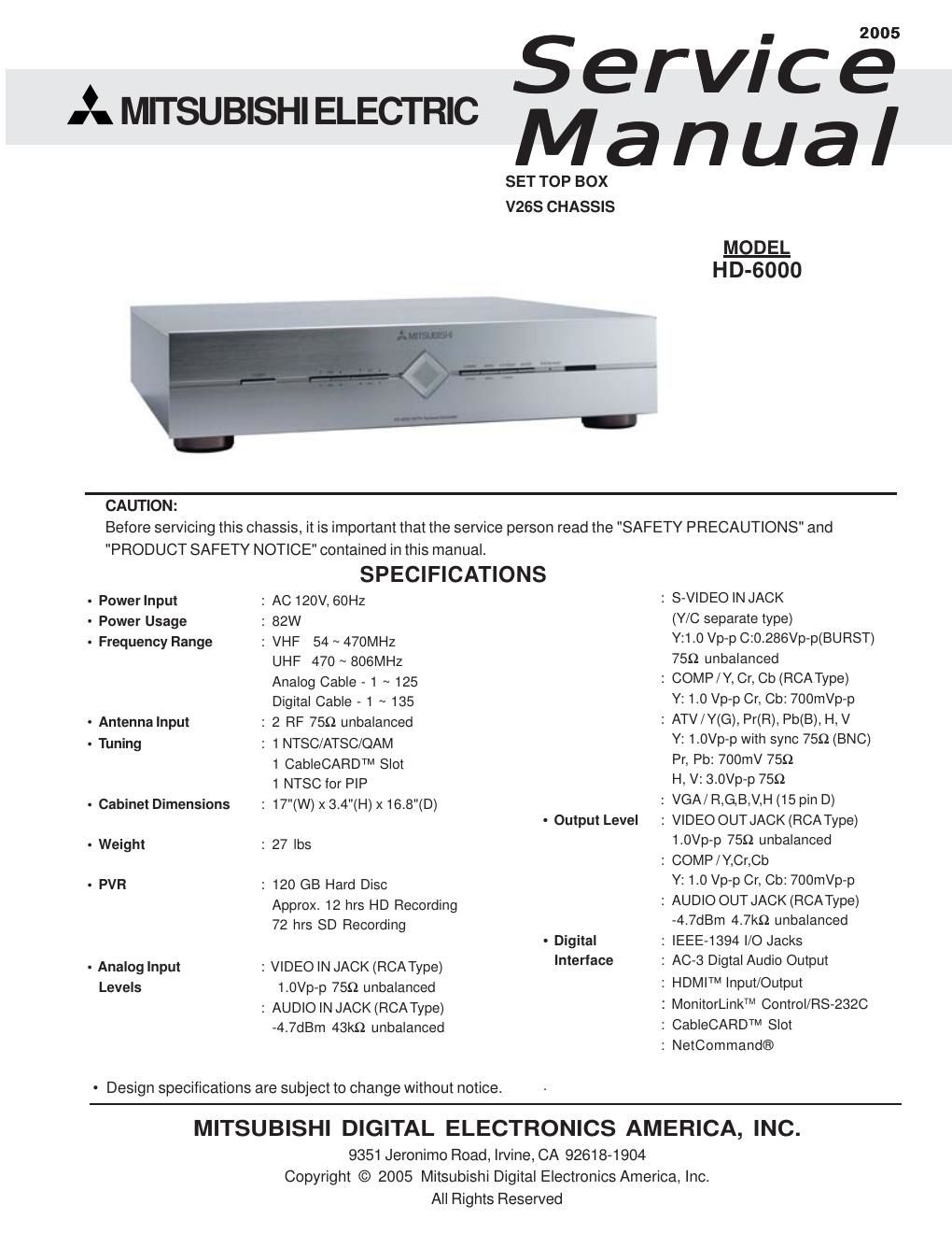
Mitsubishi hd 6000 service

This is the 53 pages manual for mitsubishi hd 6000 service.
Read or download the pdf for free. If you want to contribute, please mail your pdfs to info@audioservicemanuals.com.

Page: 1 / 53
left right
mitsubishi hd 6000 service

Extracted text from mitsubishi hd 6000 service (Ocr-read)


Page 2

MODEL: HD-6000

m
INTRODUCTION .....
PRODUCT SAFETY NOTICE ............................................................................................................. 5
SAFETY PRECAUTIONS .....
PWB-LOCATIONS ............................................................................................................................. 7
DISASSEMBLY ............................................... 7
Disassembly Procedures Sequence 7
Top Cover removal .................................. 8
HDD (Hard Drive) removal ...... 9
PWBS removal .................... O
ELECTRICAL ADJUSTMENTS ........................................................................................................ 11
Equipment ................................................................ 11
Option Menu / Initialization Defaults /AV Defaults .. . 12
LED Diagnostics ................................ . 13
Remote Control Operational Mode . . 13
CircuitAdjustment Mode ...... . 14
Transfering data ......... . 15

....15
....16
.16

Adjustment Items List
Adjustment Procedures
Test Points

Main-Y Gain . 16

Sub-Y Gain .17

Sub Picture Offset 17

CHIP PARTS REPLACEMENT ......................................................................................................... 18
REPLACEMENT PARTS ...... 19
Parts Ordering .................. . 19
Critical and Warranty Parts Designation . 19
Parts Tolerance Codes ............................. 19

SERVICE PARTS LIST .................................................................................................................... 20

CIRCUITRY BLOCK DIAGRAMS
Standby Power Supplies ......
PWB-DM Power Supplies .
PWB-SIGNAL Switched Power upp Ies .
Video Select Circuitry
Video Output Circuitry....
Sync Signal Selection ..........
Sync Signal Output Path ..
Record Signal Path

29

.29
.30
.30
.31
....32
....33

.34
.34

Sound Signal Path ..... 35
Control Circuitry ................... 36
Command Input Circuitry .37
Macrovision Detection ............... 37
PWB-DM Signal Path ................................................................................................................... 38

Page 3