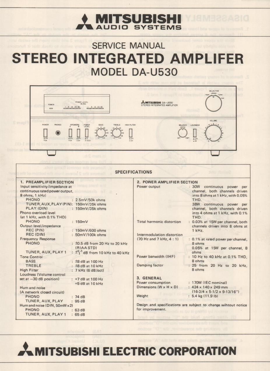
Mitsubishi da u530 service en

This is the 8 pages manual for mitsubishi da u530 service en.
Read or download the pdf for free. If you want to contribute, please mail your pdfs to info@audioservicemanuals.com.

Page: 1 / 8
left right
mitsubishi da u530 service en

Extracted text from mitsubishi da u530 service en (Ocr-read)


Page 2

DA-U530 l

DISASSEMBLY INSTRUCTIONS

1. Removal of upper and lower covers
(1) Remove the 4 screws holding the upper cover.
Slide the upper cover backward while lifting the
rear side slightly up.
Note: A lock washer is used with the screw on
the right side.
(2) To remove the lower cover, take out the 2 mount-
int screws.
2. Removal of rotary switch mechanism
The rotary switch is fastened at the rear with the 3
parts as shown in Figure 1. Eadi part is secured with
the 8 locks ("A") as illustrated in Figures 1 and 2.

Switch
Front panel @ connector ,_

@i r»

(>3

Figure 2

a. Remove the upper cover as noted in Item 1-(1).
b. Release the lock "A" shown in Figure 1.

(1) Insert a small screwdriver into the "B" section
shown in Figures 1 and 2 to remove the "A"
section by lifting it up as shown in Figure 2.

(2) After lifting, hold the "C section by hand
and insert the screwdriver into the "D section.
Bv pinching the screwdriver, the "D" section
can be removed.

:2. When reassembling, make sure that the "Asection
shown in Figure 3 is positioned on the rear side.

3.

Turn' the shaft on the panel counterclockwise.

Set the notch in the switch to the "A" section
shown in Figure 3 and then insert the switch unit.
Turn the rotary switch to check that it functions
properly.

Switch unit

Notch in switch Figure 3

Removal of front panel assembly

b

rumor)


Remove the upper cover as noted in Item 1-).

. Release the lock on the rotary switd1 panel as noted
in Item 2-b.

Pull and remove each rotary knob.

. Remove the control fixing nuts.

Remove the 2 screws from the bottom of the panel.
While pulling the left side panel outward, slide out
the front panel in the forward direction.

To disassemble completely, remove the screw
holding the lug terminal with black lead shown in
Figure 4, then remove the screw holding the
POWER and LEVEL indicating plate.

Lug terminal
with black lead

Remove this screw

(AS) Australia
(SN) Singapore
(U.K.) United Kingdom
(WG) West Germany