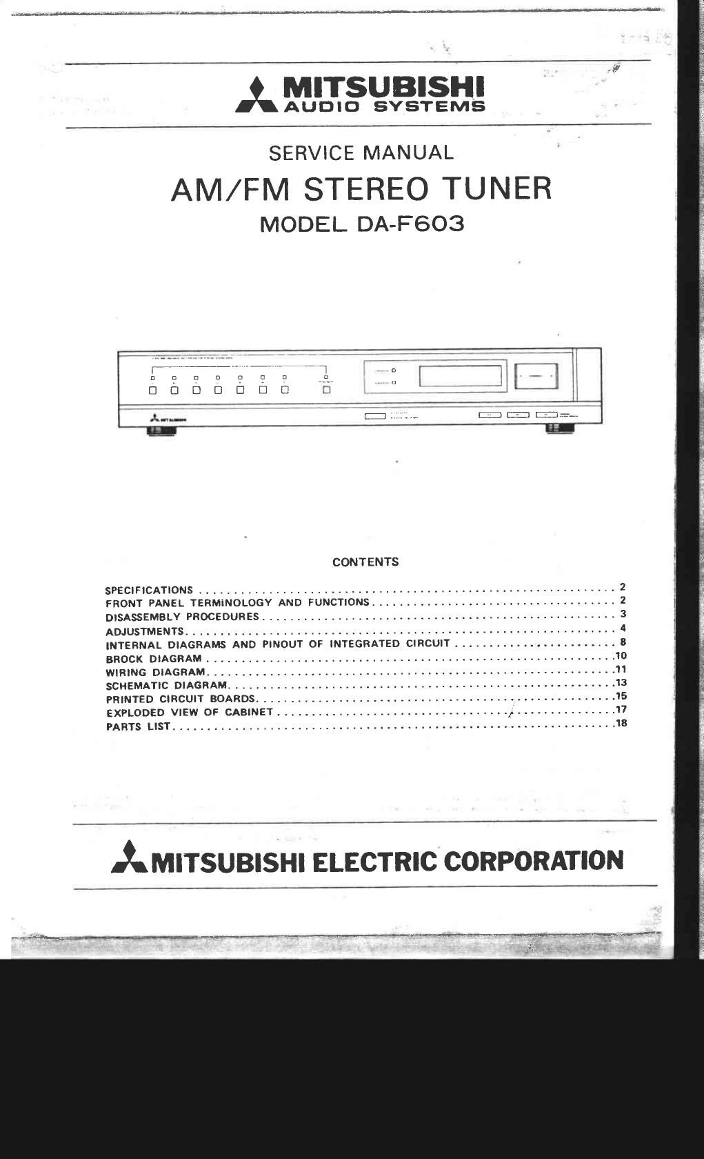
Mitsubishi da f603

This is the 22 pages manual for mitsubishi da f603.
Read or download the pdf for free. If you want to contribute, please mail your pdfs to info@audioservicemanuals.com.

Page: 1 / 22
left right
mitsubishi da f603

Extracted text from mitsubishi da f603 (Ocr-read)


Page 1

MI I SU BISHI I,
A AUDIO SYSTEMS
A 77 , 7 7 ,,,,,, 7, LE _ _,I
_ ° i I :1 '
n a c c: a :7 J1 v I

E] D D D D E] D C' T

.u-.. if '7 7 7:: -.:,, 331;

n

CONTENTS

SPECIFICATIONS ............................................................. 2
FRONT PANEL TERMINOLOGY AND FUNCTIONS .................................... 2
DISASSEMBLY PROCEDURES .................................................... 3
ADJUSTMENTS ............................................................... A
INTERNAL DIAGRAMS AND PINOUT OF INTEGRATED CIRCUIT ........................ 3
BROOK DIAGRAM ............................................................ 10
WIRING DIAGRAM ............................................................ I'I
SCHEMATIC DIAGRAM ......................................................... 13
PRINTED CIRCUIT BOARDS ..................................................... 15
EXPLODED VIEW OF CABINET .................................. x ............... 17
PARTS LIST ................................................................. 18

AMITSUBISHI ELECTRIC CORPORATION

Page 2

A.-F603

ADJUSTMENTS
No 1:2:1 Input/Output and procedure Azarnnfim AdII-lflmml '0'
, 1 AM 0 Set the IF sweep frequency to 455kHz T5 Adjust T5 and T8 so that the
I IF j C Connect IF sweeps OUT terminal to TB waveform is maximum and
2 Adjustment j loop antenna E symmetrical as in Fig. 4.
[MW model i Connect IF sweep's IN terminal to TPl. I
(Fig. 5i
2 FM 0 Set the IF sweep frequency to 10.7MHz. T6 Adjust T6 and T7 so that the
r IF 0 Connect lF sweeps OUT terminal to T7 . sweep waveform is maximum
. j Adjustment the FM antenna terminal through the 3009 and symmetrical as in Fig. 5.
'V [FM mode] balanced dummy. (signal level 1 mV)
f (Coarse) IF sweep's IN terminal to TP2 and
l IF sweep's ground terminal to TP7 (GND)
lFig. 7i
3 FM VCO l 0 Connect digital voltmeter across TPS
Check and TP7 (6ND) (Fig, 8)
j l 0 Set the function to the FM position, the
1 reception frequency to BSMHZ and check
that voltage is 1.6 1 0.05V.
'. I Set frequency to 108MHz and check that
'~ I the voltage is 8 t OOSV.
. r
4 FM IF r 0 Set the FM signal generator to SSMHz and TE I Adjust for minimum distortion.
j Adjustment connect to the FM antenna terminal T7
[FM model through the 3009 balanced dummy. (Signal
(Fine) level 1 mV)
0 Set the function to the FM position and the
reception frequency to QBMHz.
l 0 Connect a distoution meter to the audio
I: output of the onetouch connector, (Fig. 9)
5 MW VCO 0 Connect digital voltmeter across TPS and T3 Adjust T3 until voltage becomes
1' Adjustment TP7 (GND). (Fly. 8) 0.9 1' 0.05V.
I 0 Set the function to the MW position, and
the reception frequency to 522kHz (min.
ll frequency).
l I 0 Set the reception frequency to 1,611kHz TC3 Adjust T63 until voltage becomes
, (max, frequency). 9.14 i 0.05V.
0 Repeat the above adjustments two or three times until both adjustments are at best level.
6 MW 0 Radiate each of the tracking point fre~ TI Adjust so that the output is
Tracking quencies given below from the AM test loop TCI maximum at each tracking point,
Adjustment (signal level 56dB/mi
0 Receive each of the tracking point Ire-
I . quencies given below by means at the key
-'- or Tuning Up/Down Switch.
0 Connect the AC voltmeter to the audio
output of onetouch connector. (Fig. 10)

.. me... my. min-«t