Micro seiki ma 505 service manual

This is the 2 pages manual for micro seiki ma 505 service manual.
Read or download the pdf for free. If you want to contribute, please mail your pdfs to info@audioservicemanuals.com.

Page: 1 / 2
left right
micro seiki ma 505 service manual

Extracted text from micro seiki ma 505 service manual (Ocr-read)


Page 1

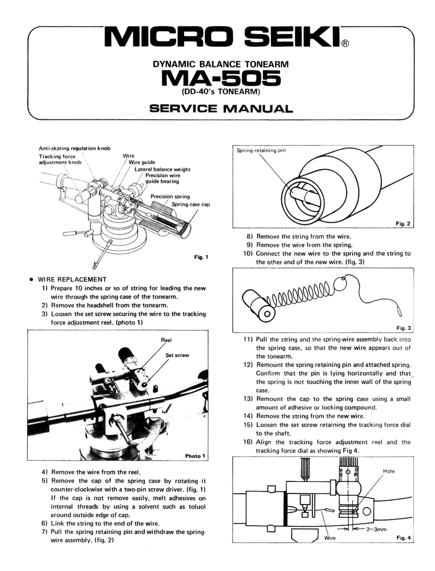
Anti-skating regulation knob
Tracking force Wire
adiustrnent knob ,' Wire guide

Lateral balance weight
. .72.. . Precision wire
,7. p gurde bearing

,_ (4%? _ . hyf 1-1"; alcéljjv
.- "t i. v \
J, 7 (M1 " \K'rk 0%,: . Precision spring
'~ \. flip; syn; ,- Spring case cap
.. g) «.1». 1..


fig;

0 WIRE REPLACEMENT
1) Prepare 10 inches or so of string for leading the new
wire through the spring case of the tonearm.
2) Remove the headshell from the tonearm.
3) Loosen the set screw securing the wire to the tracking
force adjustment reel. (photo 1)

Reel

Set screw

'J

j H" ___Ph_oto 1 l

4) Remove the wire from the reel.

5) Remove the cap of the spring case by rotating it
counter-clockwise with a two-pin screw driver. (fig. 1)
If the cap is not remove easily. melt adhesives on
internal threads by using a solvent such as toluol
around outside edge of cap.

6) Link the string to the end of the wire.

7) Pull the spring retaining pin and withdraw the spring-
wire assembly. (fig. 2)

I
,
\I

'3' 4

I;

/ MICRO SEIKI®

DYNAMIC BALANCE TONEARM

MA-EDE

(DD-40's TONEARM)
K SERVICE MANUAL

Spring retaining Din

Fig. 2

8) Remove the string from the wire.
9) Remove the wire from the spring.
10) Connect the new wire to the spring and the string to
the other end of the new wire. (fig. 3)

Fig. 3 _

11) Pull the string and the spring-wire assembly back into
the spring case, so that the new wire appears out of

the tonearm.
12) Remount the spring retaining pin and attached spring.

Confirm that the pin is lying horizontally and that.

the spring is not touching the inner wall of the spring
case.

13) Remount the cap to the spring case using a small
amount of adhesive or locking compound.

14) Remove the string from the new wire.

15) Loosen the set screw retaining the tracking force dial
to the shaft.

16) Align the tracking force adjustment reel and the
tracking force dial as showing Fig 4.

--- . - -_._..__

Page 2

17) Turn the anti-skating regulation knob counter-clock-
wise until it stops.

18) Thread the wire through as shown in Fig. 5 and insert
the end pipe of the wire into the hole on the tracking
force adjustment reel and secure it with the set screw.
Confirm that the end pipe of the wire does not ap-
pear out of the hole.

Wire Pipe
2::\
p v
/ x
@O/ I, &\
'
\
\
~--

I Fig. 5
0 TRACKING FORCE CALIBRATION
Using a balance (a beam and scales), calibrate the tracking
force dial as following procedures;

1) Remount the haadshell with the cartridge to the tone
arm, but to prevent damaging the stylus, remove the
stylus by pulling it forward out of the cartridge.

2) Turn the counterweight of the tonearm until the tone-
arm balance is achieved.

3) Place the cartridge on one side of the scale and a 1
gram weight on the other side. If the cartridge body
dose not rest on the scale due to the tonearm pipe
touching the scale edge, mount a suitable flat plate on
the scale as shown in Fig. 6 and balance it again, before
weighing 1 gram.

Flat plate

1 gram weight

Lea.)

\

~ .

"-

4) Turn the tracking force adjustment knob until the bal-
ance keeps level.

5) Align the 1 mark on the dial with the referenceline
after loosing set screw. During the alignment hold the
reel so that the wire does not get loose.

6) Secure the tracking force dial to the shaft with the set
screw.

0 SPECIFICATION

Model Dynamic balance type
universal tone arm

Total length 322 mm (12-11/16)
Working length 237 mm ( 9-5/16")
Ovefhang 15 mm (IQ/32)
Offset angle 21° 50'

Angle of Less than 1.5°

tracking error

Height adjustment

range 42-86 mm (1-5/8"~3-3/8")
(measured from the motor board
to the cartridge installation surface)

Height adjustment

range achieved by

lever operation

Suitable cartridge

6 mm (1/4")

weight 4-10 9 (0.14~0.35 02)
Using sub-weight

(large) 9.5-16 g (0.34~0.56 0:)
Horizontal move-

ment sensitivity 25 mg

Vertical movement

sensitivity 25 mg

Tracking force rev

gulation range 0-3 9 scale

Anti-skating device Spring tension system regulated
according to tracking force

Arm lifter Built-in shock absorber for raising
Slow return type
Headshell turning mechanism
installed

Output lead Low capacity 5P plug in

(55 pF/m) shielded cord
Headshell weight 9.7 g (0.34 oz)
Head connector SME type 4P connector
Connector Electroplated in hard metal

Distributed in U.S.A. by

(3' MICRO SEIKI (30., LTD. TEAC CORPORATION OF AMERICA 7733 Telegraph Road. Montebello. Ca. 90640

TDKYn-. lAPAN

Dninf-cv-l in . IADARI