Page 1
Low Voltage Wiring Instructions for DSP420
NB. THE PRE-ASSEMBLED TERMINAL BLOCK SHOULD BE UNPLUGGED FROM THE PCB SOCKET PRIOR TO CONNECTION
The DSP420 requires the following connections:
1. Comms Input (pins 9&10)
2. Digital Audio Input (pins 13&14)
The Slave link (Pins 7&8) should be fitted for a Slave speaker and removed for a Master speaker.
If it is to be daisy-chained to a further speaker it requires the following additional connections:
3. Comms Output (pins 5&6)
4. Digital Audio Output (Pins 11&12)
If IR input is required from a sensor such as a Meridian 512, this can be connected to pins 1 to 3.
Typical connections are shown in the diagrams below.
1 +8V (50mA) 2 Ground For connection to an IR 3 IR In Receiver e.g. a Meridian 512 4 Ground 5 Comms Out Comms Output to next speaker in 6 C.O. Ground pair (see below) 7 Slave Link Slave Link -� Remove if Master Speaker 8 Slave Link Fit if Slave Speaker (fitted as default) 9 Comms In Comms Input from speaker or system 10 C.I. Ground (see below) 11 Dig Out Digital Output to next speaker 12 D.O. Ground 13 Dig In Digital Input from other speaker or 14 D.I. Ground system
Meridian Digital Link is a suitable cable for the Comms and the Audio but is not UL approved. If alternative cable is
needed, the following specifications should be followed.
Comms: Single screened cable, 100pF/m or less
Digital Audio: 75 Ohm Coaxial cable, shielded with braid and foil
Connecting a pair of DSP420s as a stereo system (M5 lead connects to system) 98765432112111014139876543211211101413M5 LEAD
S5 LEAD
MASTER
SPEAKER SLAVE
SPEAKERDigital Audio (75Ohm Coax)
Comms (Single Screened)Link FittedNo
Link
Connecting a pair of DSP420s as slaves in a theatre system (S5 lead connects to system) 98765432112111014139876543211211101413S5 LEAD
S5 LEAD
SLAVE
SPEAKER SLAVE
SPEAKERLinkLink
Connecting a DSP420 as a centre master in a theatre system (M5 and S5 connect to system) showing connection to
a 512 IR sensor 9876543211211101413M5 LEADS5 LEAD
CENTRE MASTER SPEAKERRED (+8v)Shield (Ground)BLUE (IR)
TO MERIDIAN
512Digital Audio (75Ohm Coax)
Comms (Single Screened)
IR (Dual Screened)No
Link
Stonehill, Stukeley Meadows, Huntingdon, Cambridgeshire PE29 6EX, England
Telephone 44 (0)1480 445678
Fax 44 (0)1480 445686
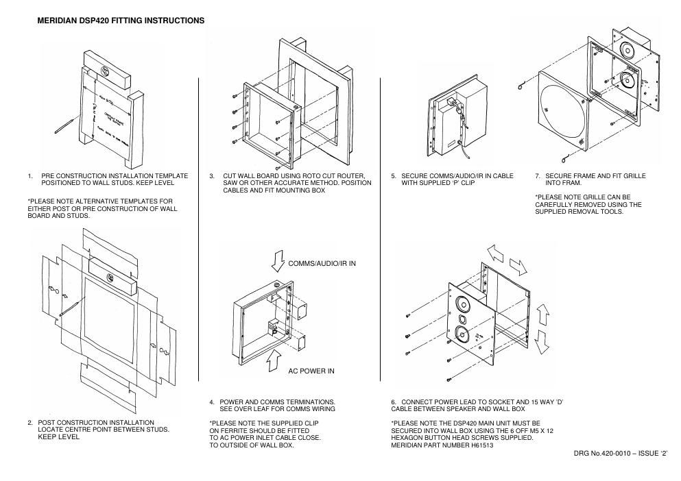
DSP420 INSTALLATION INSTRUCTIONS
This sheet is intended as a guide for installing the wall box for the DSP420 including:-
- Use of the template to cut the correct hole in the wall board
- Fitting the back box to the wall studs
- General wiring instructions for comms and audio
- Fitting the speaker and grille to the back box
Please note: This product is recommended to be a 2 person installation
Pleaese also note: Thid product is not designed for ceiling installation
IMPORTANT SAFETY INSTRUCTIONS
Read the instruction
Keep these Instructions
Heed all warnings
Follow all instructions
Do not use this apparatus near water
Clean only with a dry cloth
Install only in accordance with the manufacturers instructions
Only use with a Meridian Audio DSP420 digital active loudspeaker
Refer all servicing to approved service personnel
Connection to the mains should be carried out by a skilled and suitable qualified person
Refer all servicing to qualified service personnel. Servicing is required when the apparatus has
been damaged in any way, such as power-supply cord or plug is damaged, liquid has been
spilled or objects have fallen into the apparatus, the apparatus has been exposed to rain or
moisture, does not operate normally, or has been dropped.
WARNING: TO REDUCE THE RISK OF FIRE OR ELECTRIC SHOCK, DO NOT
EXPOSE THIS APPARATUS TO RAIN OR MOISTURE.