McIntosh MX 99 Service Manual

This is the 12 pages manual for McIntosh MX 99 Service Manual.
Read or download the pdf for free. If you want to contribute, please mail your pdfs to info@audioservicemanuals.com.

Page: 1 / 12
left right
McIntosh MX 99 Service Manual

Extracted text from McIntosh MX 99 Service Manual (Ocr-read)


Page 1

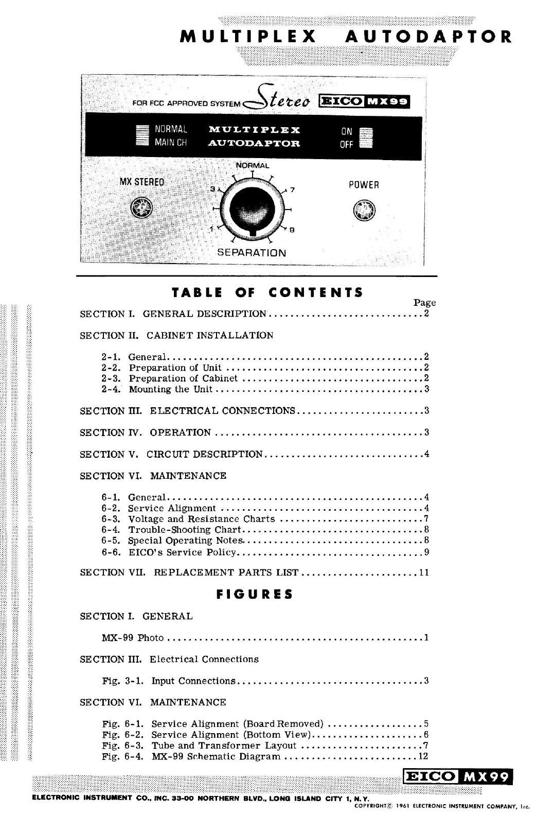
MULTIPL'EX AUTo'b'AéTOR

FDR FCC APPROVED SYSTEM éle t6 0

NURMAL MULTIPLEX
MNN CH AUTODAPTOR

SEPARATION

TABLE OF CONTENTS

Page
SECTION I. GENERAL DESCRIPTION ............................. 2
SECTION II. CABINET INSTALLATION
2-1. General ...... ............ . .............. 2

2-2. Preparation of Unit . . . . . . . . . . . . . .
2-3. Preparation of Cabinet .. . ..

2-4. Mountingthe Unit.. ...... 3
SECTION III. ELECTRICAL CONNECTIONS ........................ 3
SECTION IV. OPERATION ....................................... 3
SECTION V. CIRCUIT DESCRIPTION. ............................. 4

SECTION VI. MAINTENANCE


6- 1. General ................................................ 4
6-2. Service Alignment ................. . . . 4
6-3. Voltage and Resistance Charts ........................... '7
6-4. Trouble-Shooting Chart .................................. 8
6-5. Special Operating Notes. . . . . 8
6-6. EICO's Service Policy ................................... 9
SECTION VII. REPLACEMENT PARTS LIST ...................... 11
F I G U R E 5
SECTION I. GENERAL
MX-99 Photo ................................................ 1
SECTION III. Electrical Connections
Fig. 3-1. Input Connections ................................... 3
SECTION VI. MAINTENANCE
Fig. 6-1. Service Alignment (BoardRemoved) ...... . . 5
Fig. 6-2. Service Alignment (Bottom View). . . . . 6
Fig. 6-3. Tube and Transformer Layout . . . . . . .7
Fig. 6-4. NIX-99 Schematic Diagram ......................... 12

99

ELEOYRONIC INSTRUIIENT 60., mo. 33-00 NORTHERN BLVD.. LONG ISLAND CITY 1, N.V.
commune; nu ElECIlONIC msuummr coMuNY, luzl

Page 2

PAGE 2

INSTRUCTION BOOK

SECTION I. GENERAL DESCRIPTION

The new EICO MIX-99 MultiplexAutodaptor*employs
an original method of zero phase shift, filterless detec»
tion of multiplexed signals. The unit automatically
delivers stereo on a stereo broadcast signal, and mono
from a mono signal without spurious signals in either
case. The stereo signal is automaticallygain-balanced
and the mono signal is automatically equal from both
outputs without adjustment. An indicator lamp turns
on when the station selected is broadcasting multiplex
stereo.

The design features freedom from phase distorting
filters in either the main or sub channel paths which
cause loss of separation. Nevertheless this design
provides the required, or better-than-required, sup-
pression of all spurious signals including SCA (67kc)
background music carrier, reinserted 38kc sub-car-
rier, 19kc pilot carrier, and all harmonics thereof.
This is achieved partly through an original technique
for deriving the left and right signals, and partly by
sharp ultrasonic filters after the signals are derived.
All of the foregoing is very important for high quality
tape recording, where spurious signals can beat against
the tape recorder bias oscillator and result in audible
spurious tones in a recording. This adaptor will syn-
chronize with any usable output from the FM tuner
and will demodulate without significant distortion tuner
(composite signal) as high as 5 volts peak-to-peak.

The MX-99 is self powered, and includes low
impedance cathode follower outputs. Externalcontrols
include an oscillator turn-off switch to permit inter-
fercnce~free listening to mono stations having low
sub-carrier frequency SCA store-casting anda scpar-
ation control. A separation of 30db between channels
is typical and an overallgain of unity is provided from
input to output on both stereo and mono. The NIX-99
is designedfor all EICO FM equipment (HFT90, HFT92,
STQG), and any other component quality, wide band FM
tuner provided with a multiplex output.

Tubes: 2-12AU7, l-IZAT'I, i-6AU6, 1-6D10, 1-6X4
and 6 diodes

Size (HWD): 3-7/8" x 9~ 1/8 x 6-3/8"
Weight: 7 lbs.

Cover: OPTIONAL

*Patent Pending

SECTION II. CABINET INSTALLATION
2-1. GENERAL

1. Mount horizontally on awell-braced shelf. The
stock thickness of the wood panel may not exceed 3/4".

2. Do not remove feet for mounting. Air must be
allowed to enter through the perforations in the bottom
plate to avoid overheating.

3. To avoid over heating when stacking components
mount the tuner below the amplifier with the NIX-99
alongside the tuner. Any shelf above the MX-99 must
be spaced at least 2 inches away. Allow at least a 1-
inch tolerance on either side of the unit.

4. Leave the back of the cabinet entirely open.

2-2. PREPARATION OF UNIT

1. Loosen the left and right side pairs of screws
(4 in all) that fasten the bottom plate and cover to the
chassis, just enough to permit the cover and bottom
plate to slide backward or forward inthe 3/4" chassis
slots.

2. Push both cover and bottom plate back as far
as they will go (3/4"). The screws that have been
loosened will move from the front to the rear ends of
the slots in the chassis.

3. Detach the knob from the separation control
shaft. Then remove the2 screws, that fasten the panel
to the chassis, one at the left of the NORMAL-MAIN
CH switch and the other at the right of the ON-OFF
switch. Take panel off and set it aside. The unit is
now prepared for cabinet installation.

2-3. PREPARATION OF CABINET

1. Twotemplates are provided, one forthe cabinet
shelf and the other for the cabinet panel. The shelf
template is used to locate exactly two holes that are
to be drilled in the shelf. The panel template is used
to locate exactly the required rectangular cut-out. The
two templates must be used together as indicated, as
there is an exact relationship between the locations of
the shelf holes and panel cut-out.

2. To use the shelf template, cut it or [old it back
exactly along the dashed line. Remove the shelf from
the cabinet and line up this dashed line on the template
with thefront edge of the shelf, positioning it also along
the edge to leave at least 1 clearance on each side.
Tape the template in position and use a center punch
to mark the centers of the two holes to be drilled. If
the shelf can not be removed, place the template in a
similar manner on the top side of the shelf ii there is
room to drill from the top side, or on the under side
of shelf if there is room only to drill from the under
side. If the template is used on the underside of the
shelf, mark the rear edge of the shelf at the points
where the extended heavy lines on the template hit the
rear shelf edge. After the holes are center-punched,
remove the template and drill carefully through the
punched centers to a diameter of 1/4". If the shelf
has been removed for the drilling operation, now re-
mount it. Finally, replace the shelf~template in exactly
its former position on the top-side of the shelf and