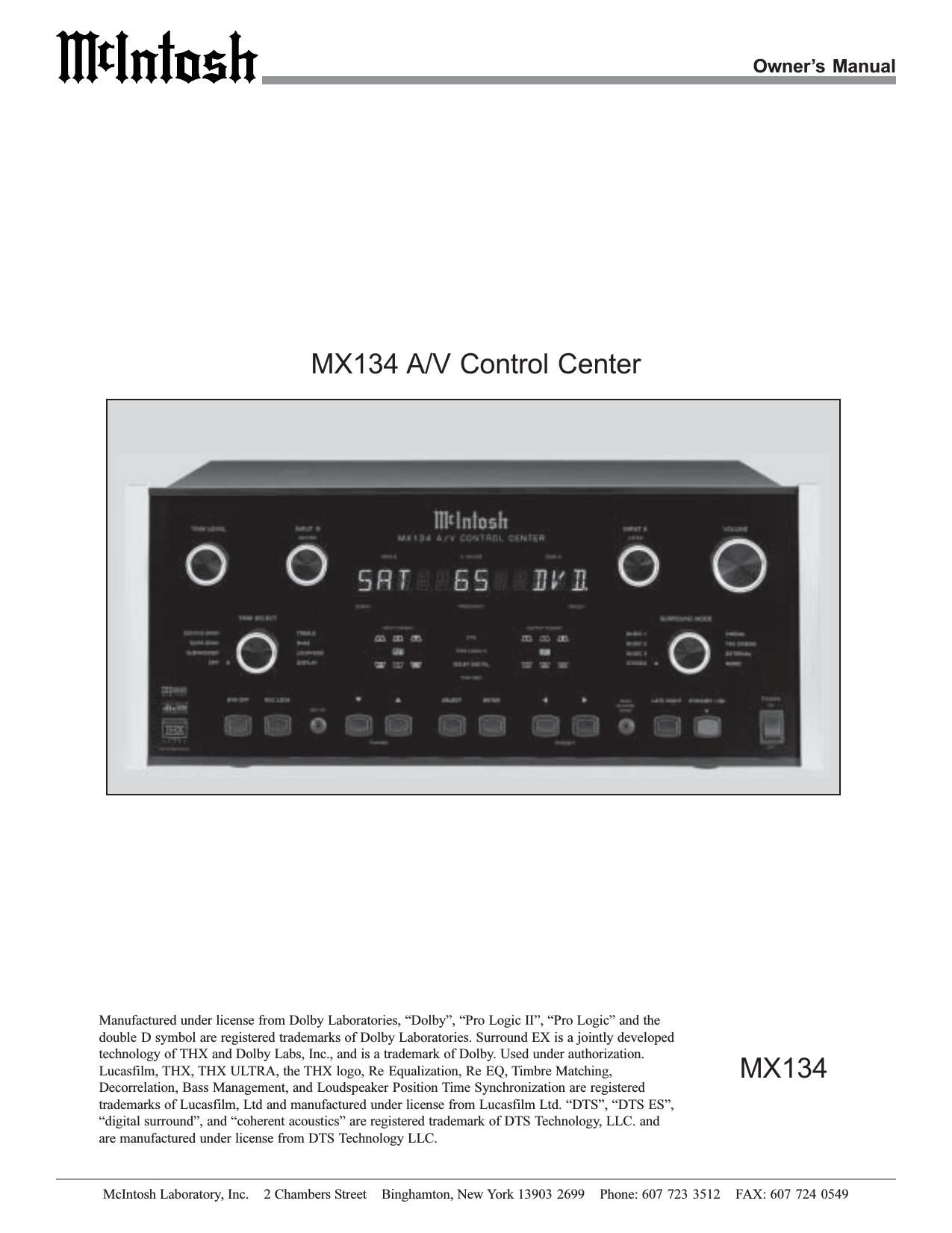
McIntosh MX 134 Owners Manual

This is the 60 pages manual for McIntosh MX 134 Owners Manual.
Read or download the pdf for free. If you want to contribute, please mail your pdfs to info@audioservicemanuals.com.

Page: 1 / 60
left right
McIntosh MX 134 Owners Manual

Extracted text from McIntosh MX 134 Owners Manual (Ocr-read)


Page 1

2 IMPOR T ANT SAFETY INSTRUCTIONS! PLEASE READ THEM BEFORE OPERATING THIS EQUIPMENT. WARNING - TO REDUCE RISK OF FIRE OR ELECTRICAL SHOCK, DO NOT EXPOSE THIS EQUIPMENT TO RAIN OR MOISTURE. The lightning flash with arrowhead, within an equilateral triangle, is intended to alert the user to the presence of uninsulated dangerous voltage within the products enclosure that may be of sufficient magnitude to constitute a risk of electric shock to persons. NO USER-SERVICEABLE PARTS INSIDE. REFER SERVICING TO QUALIFIED PERSONNEL. To prevent the risk of electric shock, do not remove cover or back. No user serviceable parts inside. The exclamation point within an equi- lateral triangle is intended to alert the user to the presence of important operating and maintenance (servic- ing) instructions in the literature ac- companying the appliance. General: 1. Read these instructions. 2. Keep these instructions. 3. Heed all warnings. 4. Follow all instructions. 5. Warning: To reduce risk of fire or electrical shock, do not expose this equipment to rain or moisture. This unit is capable of producing high sound pres- sure levels. Continued exposure to high sound pres- sure levels can cause permanent hearing impair- ment or loss. User caution is advised and ear protec- tion is recommended when playing at high volumes. 6. Caution: to prevent electrical shock do not use this (polarized) plug with an extension cord, receptacle or other outlet unless the blades can be fully in- serted to prevent blade exposure. Attention: pour pevenir les chocs elecriques pas utiliser cette fiche polarisee avec un prolongateur, une prise de courant ou un autre sortie de courant, sauf si les lames peuvent etre inserees afond ans en laisser aucune partie a decouvert. 7. Unplug this equipment during lightning storms or when unused for long periods of time. 8. Only use attachments/accessories specified by the manufacturer. Installation: 9. The equipment shall be installed near the AC Socket Outlet and the disconnect device shall be easily acces- sible. 10. Do not block any ventilation openings. Install in accor- dance with the manufacturers instructions. 11. Do not install near any heat sources such as radiators, heat registers, stoves, or other equipment (including amplifiers) that produce heat. 12. Do not use this equipment near water. 13. Do not expose this equipment to dripping or splashing and ensure that no objects filled with liquids, such as vases, are placed on the equipment. 14. Use only with the cart, stand, tripod, bracket, or table specified by the manu- facturer, or sold with the equipment. When a cart is used, use caution when moving the cart/equipment combination to avoid injury from tip-over. Connection: 15. Connect this equipment only to the type of AC power source as marked on the unit. 16. Protect the power cord from being walked on or pinched particularly at plugs, convenience receptacles, and the point where they exit from the equipment. 17. Do not defeat the safety purpose of the polarized or grounding-type plug.

Page 2

3 A polarized plug has two blades with one wider than the other. A grounding type plug has two blades and a third grounding prong. The wide blade or the third prong are provided for your safety. If the provided plug does not fit into your outlet, consult an electrician for replacement of the obsolete outlet. 18. Do not overload wall outlets, extension cords or inte- gral convenience receptacles as this can result in a risk of fire or electric shock. 19. To completely disconnect this equipment from the AC Mains, disconnect the power supply cord plug from the AC receptacle. Outdoor Antenna: 20. If an outdoor antenna is connected to the antenna ter- minal, be sure the antenna system is grounded to pro- vide some protection against voltage surges and built up static charge. In the U.S.A., section 810 of the Na- tional Electrical Code, ANSI/NFPA No. 70-1978, pro- vides information on the proper ground for the mast and supporting structure, ground for the lead-in wire to an antenna discharge unit, and size of ground conduc- tors, location of antenna-discharge unit, connection to ground electrode. For ground wire: A. Use No. 10 AWG (5.3 mm 2) copper No. 8 AWG (8.4 mm 2) aluminum, No. 17 AWG (1.0 mm 2) cop- per-clad steel, bronze, or larger as ground wire. B. Secure antenna lead-in and ground wires to the house with stand-off insulators spaced from 4 feet (1.2 meters) to 6 feet (1.83 meters) apart. C. Mount antenna discharge unit as closely as possible to where lead-in enters house.D. Use jumper wire not smaller than No. 6 AWG (13.3 mm 2) copper or equivalent when separate antenna grounding electrode is used. Care of Equipment: 21. Clean only with a dry cloth. 22. Do not permit objects or liquids of any kind to be pushed, spilled and/or fall into the equipment through enclosure openings. 23. Unplug the power cord from the AC power outlet when left unused for a long period of time. Repair of Equipment: 24. Refer all servicing to qualified service personnel. Ser- vicing is required when the equipment has been dam- aged in any way, such as power-supply cord or plug is damaged, liquid has been spilled or objects have fallen into the equipment, the equipment has been exposed to rain or moisture, does not operate normally, or has been dropped. 25. Do not attempt to service beyond that described in the operating instructions. All other service should be re- ferred to qualified service personnel. 26. When replacement parts are required, be sure the ser- vice technician has used replacement parts specified by McIntosh or have the same characteristics as the origi- nal part. Unauthorized substitutions may result in fire, electric shock, or other hazards. 27. Upon completion of any service or repairs to this prod- uct, ask the service technician to perform safety checks to determine that the product is in proper operating condition.

Page 19

20 Remote Control Push-Buttons Selects one of the twelve Audio/Video SourcesTurns AC Power ON or OFF to certain McIntosh Components when connected via the Data Port Adjusts the volume level Up or Down Selects DVD/CD Players or Tape Recorder Func- tions and also performs various functions on a variety of McIntosh Com- ponents Press to POWER the MX134 ON or OFF Use to select tuner presets, disc tracks or any numbered opera- tion Selects FM Tuner Operat- ing Functions and Track Selection on certain McIntosh CD Players Mutes the audioPress MODE to switch between various Surround Modes Selects AM Tuner Oper- ating Functions and Disc Selection on certain McIntosh CD PlayersSelects On Screen Func- tions for MX134, McIn- tosh DVD Players and certain other CD Players Press TRIM, then the LEVEL Up and Down to select and adjust various functions Selects the Fast Forward Mode on Disc Players and Tuning Up the AM/ FM Dial Selects the REWind Mode on Disc Players and Tuning Down the AM/FM Dial Selects Functions for McIn- tosh Home Controller Press the push-button to illuminate the keys Press to REVIEW Tuner Station Presets and se- lects certain functions on McIntosh CD Players

Page 24

25 SETUP, cont How to Adjust for Loudspeaker Size A Home Theater System can include a variety of Loud- speakers with various capabilities. The LARGE listing re- fers to the Loudspeakers capability for reproducing bass frequencies down to 35Hz within -3dB of the midrange fre- quencies. If a Loudspeaker can not reproduce bass frequen- cies down to 35Hz within -3dB of the midrange frequen- cies, it is considered SMALL. If you do not have a Subwoofer, you must have Front (Left and Right) Loud- speakers that are LARGE in order to hear the low frequen- cies below the Subwoofer Crossover Setting of 80Hz. If you are unsure as to the bass performance capabilities of your Loudspeakers, select the SMALL setting. 1. Press and hold the Front Panel SETUP Push-button ap- proximately three seconds to enter the Setup Mode. The word SETUP will appear on the MX134 Front Panel Alphanumeric Display and the MAIN SYSTEM SETUP Menu will appear on the Monitor/TV screen. Refer to figure 6 on page 23. 2. Using the Up or Down directional push-buttons, select Speaker Size on the On-Screen Menu, followed by the SELECT Push-button on the Remote Control. Refer to figure 8. Notes: The very first time the SPEAKER SIZE MENU is accessed, the factory default settings will be indicated. In the Speaker Size Menu Setting Options, the number after the name of Small or Large refers to quantity of Loudspeakers. If the setting for the Back Surround Loudspeaker is Small 1,only the Zone A Back Output Left Channel will have audio output. 3. Select the appropriate Loudspeaker location and type by using the Up or Down directional push-buttons to select first the menu item and then press the Left or Right directional push-buttons to change the cur- rent setting. Notes: When the Front Loudspeakers are set to Small, the options in the Speaker Size Setup Menu for the Center and Surround Loudspeakers are Small or None; the Subwoofer Loudspeaker will be set to the On position. If the Surround Loudspeakers are set to Small, the options in the Speaker Size Setup Menu for the Back Surrround Loudspeaker are Small 1(BSL), Small 2(THX) or None. When the Small 1 (BSL) setting is selected, the BACK Surround Right Channel ZONE A OUTPUT will be switched Off. 4. When all of the settings on the SPEAKER SIZE MENU agree with the Loudspeakers in your Home Theater System, perform the Sub Crossover and/or the MC Bass Mode adjustments below or if no adjustments are needed, then continue to the SPEAKER TIME DELAY Settings. If you do not wish to perform SPEAKER TIME DELAY adjustments at this time, select MAIN MENU from the menu. The MAIN SYSTEM SETUP Menu will reappear on the Monitor/TV screen and pro- ceed to the next step. 5. Select EXIT from the MAIN SYSTEM SETUP Menu. If you are satisfied with the changes that you may have made, select YES to save those changes or NO not to save them. The MX134 will then return to normal op- eration. Refer to figure 7 on page 25. Sub Crossover The MX134 incorporates a built-in Electronic Crossover. The Crossover will redirect all of the audio frequencies be- low the crossover frequency setting to the Subwoofer and all the frequencies above the setting to the appropriate re- maining Home Theater Loudspeakers. The default setting for the SUB CROSSOVER frequency setting is 80 Hz, which is the correct frequency for most Home Theater Loudspeaker Systems. Refer to figure 8 and perform the following steps to change the setting. 6. Using the Up or Down directional push-buttons, select SUB CROSSOVER from the Speaker Size On- Screen Menu, followed by pressing the Left or Right directional push-buttons to change the cross- over frequency to the desired setting. Notes: The range of adjustment is from 60Hz to 120Hz in 10Hz increments. When the Input Source is Analog and the Surround Mode is set to STEREO (the Alphanumeric Front Panel Display will indicate PURE STEREO) the crossover frequency will default to 80Hz. Figure 8 MENU: SPEAKER SIZE FRONT: Small{THX} CENTER: Small{THX} SURROUND: Small{THX} BACK SURROUND: Small2{THX} SUBWOOFER: Yes SUB Crossover:80Hz{THX} MC BASS MODE OFF MAIN MENU

Page 41

42 center of the front panel display. Zone B is not affected by the front panel VOLUME Control. Zone B (Record) vol- ume level is adjusted only in Zone B with a Remote Con- trol or Keypad. Refer to figure 36. System Off Normally, Remote Zones are turned On and Off individu- ally in each respective zone by pressing the Power Push- button on a Keypad or Remote Control. If you desire to switch Off all zones of an entire McIntosh System simulta- neously, including a control center and accessory source components, you can press the SYS OFF Push-button on the MX134 Front Panel. Refer to figure 36. Note: The Sys Off Push button on a Keypad or RemoteControl may also be used to switch Off the entire system. Record Lock The RECord LOCK Push-button allows for disabling of the INPUT B (record, Zone B) Selector Switch while a record- ing is in process. Setup Pressing the SETUP Push-button activates the MX134 SETUP Mode for making changes to the Home Theater System. Tuning  The TUNING Up  and Down Push-buttons allow for tuning to the next FM or AM Radio Station when the op- tional TM1 Tuner Module is installed. Select When the MX134 has the optional TM1 Tuner Module in- stalled, the SELECT Push-button allows for selecting ei- ther the FM or AM Broadcast Bands. Enter When the MX134 has the optional TM1 Tuner Module in- stalled, the ENTER Push-button is used for entering an AM or FM Broadcast into memory. Preset   The PRESET Left  and Right  Push-buttons allow for selecting the next FM or AM Radio Station that has been stored into memory, when the optional TM1 Tuner Module is installed. Back Channel Mode The BACK CHANNEL MODE Push-button on the Front Panel of the MX134 permits the temporary override of the MX134 Setup Menu Surround Mode Setting. The Back Channel Surround Pro- cessing may be switched On or Off, when the SURROUND MODE Selector is set to the THX CINEMA position. After the MX134 is placed into standby and switched back On, the status of the Back Surround Loudspeakers will revert to the Setup Menu Surround Mode Setting. Refer to figures 37, 38 and 39. Note: The Surround Mode THX and/or DTS Menu Settings in the MX134 SETUP need to be set to either On or Auto in order to repr oduce the Back Channel Sur round Information. If the incoming Digital Signal contains a DTS Discrete ES Sound Track, the MX134 will automatically switch On the Back Surround Channels regardless of the BACK CHANNEL MODE Selection of On or Off. Figure 37 Figure 36

Page 47

48 How to Operate Zone B The MX134 includes the feature of being able to operate and control two Audio/Video Zones, independent of each other. Zone A is designed to be the Primary (Home Theater Listening Area) with Surround Sound capability. Zone B is configured for a Secondary Remote Location providing two channel audio and video programs.The program source selected for Zone A appears on the right side of the MX134 Front Panel Alphanumeric Dis- play, and the program source selected for Zone B appears on the left side. Zone A Sources are selected by using the INPUT A (Listen) Selector Switch and the Zone B Sources are selected by using the INPUT B (Record) Selector Switch. Refer to figure 72. 1. Zone B may be switched On or Off by pressing the POWER Push-button on the Keypad or using a Remote Control aimed at a Sensor located in Zone B. When Zone B is switched On the MX134 Front Panel Dis- play will indicate ZONE B ON if Zone A is not active. Refer to figures 73, 74 and 75. Note: Zones A and B may be Turned Off by pressing the SYS Push button on the Front Panel, Keypad or using the Remote Control. Refer to figures 71, 73 and 74. Source selection may also be accomplished from the MX134 Front Panel INPUT B (Record) Selector. The separate INPUT B (Record) and INPUT A (Listen) Switches allow for the making of a recording from one pro- gram source while listening to another. You can also listen (monitor) to the recorded signal off the tape, a fraction of a second later, during recording when a three head tape re- corder is used. Refer to figure 71.1. Select the desired program source to record with the front panel INPUT B RECORD selector switch. 2. Press the REC LOCK (Record Lock) Push-button to disable any Zone B sensors or Keypads to avoid a Zone B selection interfering with the recording pro- cess. Note: If there is no Zone B connected in your system this step can be omitted. 3. Adjust the record level using the tape recorder volume control. 4. To monitor the tape during recording with a three head tape recorder, or playback the tape just recorded, turn the INPUT A LISTEN switch to select the recorder used to make the tape. Note: The MX134 RECORD OUTPUTS are not affected by the VOLUME control. To listen to a different program source while recording, turn the LISTEN switch to the desired source. The recording process will not be affected and will continue. How To Make A Tape Recording Figure 71 Figure 73 Figure 72

Page 50

51 Notes

Page 56

57 The McIntosh RAA1 Remote AM Antenna is designed to provide the best in AM Reception especially if the tuner or A/V unit is located in a noisy reception area. Locate the RAA1 away from all electronic and electrical interference sources. Rotate the AM Antenna to reduce interference and receive maximum signal strength. Notes: The RAAI Remote AM Antenna of the TM1 has been factory adjusted for optimum reception in a typical urban location. If you wish to customize the AM Antenna for the best possible performance in your location, have your dealer perform the two adjustment operations listed below. An additional long wire AM antenna or external ground can be connected to the GND and ANT terminals if desired. 1. Tune to a weak AM station near 600kHz on the AM band. Using an appropriate NON - How to Optimize AM Reception Figure 84 METALLIC tool, adjust the 600kHz Transformer L1 for maximum signal strength. Refer to figure 84. 2. Tune to a weak AM station near 1400kHz on the AM band. Using an appropriate NON - METALLIC tool, adjust the 1400kHz Trimmer Capacitor C1 for maxi- mum signal strength. 3. Repeat steps 1 and 2 until no further improvements can be obtained. Preset Number Frequency City Call Letters Name FM 1 FM 2 FM 3 FM 4 FM 5 FM 6 FM 7 FM 8 FM 9 AM 1 AM 2 AM 3 AM 4 AM 5 AM 6 AM 7 AM 8 AM 9 FM and AM Station Presets How to Optimize AM Reception