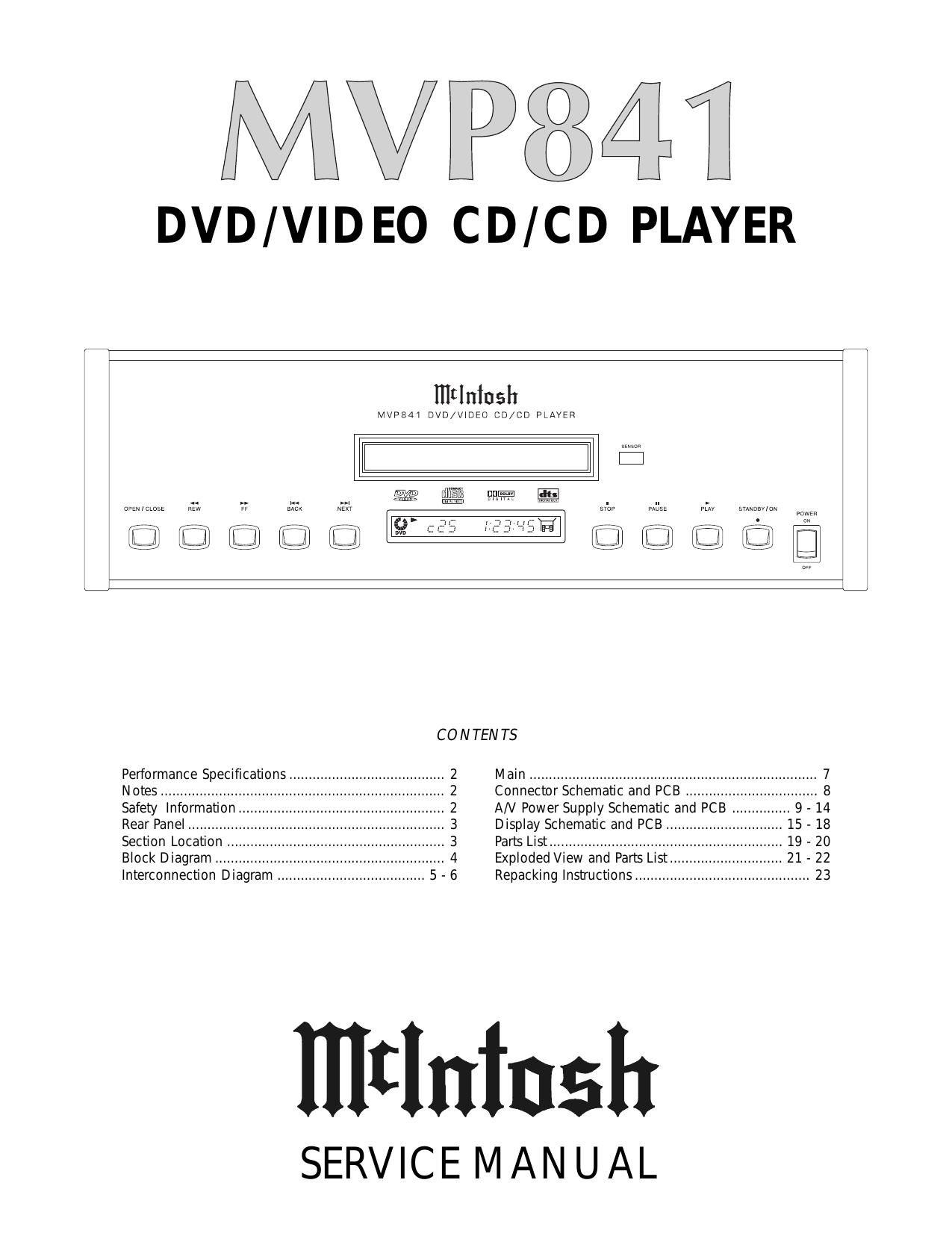
McIntosh MVP 841 Service Manual

This is the 14 pages manual for McIntosh MVP 841 Service Manual.
Read or download the pdf for free. If you want to contribute, please mail your pdfs to info@audioservicemanuals.com.

Page: 1 / 14
left right
McIntosh MVP 841 Service Manual

Extracted text from McIntosh MVP 841 Service Manual (Ocr-read)


Page 1

PERFORMANCE SPECIFICATIONS 2 VIDEO SPECIFICATIONS Signal System: NTSC Component Video Y Output Level: 1Vp-p (75 ohm) Component Video PB Output Level: 0.7Vp-p (75 ohm) Component Video PR Output Level: 0.7Vp-p (75 ohm) Output Connector: RCA Jack (Y: Green, PB: Blue, PR: Red) S-Video Output Level: 1Vp-p (75 ohm) S-Video C Output Level: 0.286Vp-p (75 ohm) (NTSC) Output Connector: Mini DIN Video Output Level: 1Vp-p (75 ohm) Output Connector: RCA Jack AUDIO SPECIFICATIONS Number Of Channels: 2 Output Level: 2.2Vrms DVD Frequency Response: 4-22kHz (48kHz Sampling, Linear Audio) 4-44kHz (96kHz Sampling, Linear Audio) CD Frequency Response: 4-20kHz CD Signal To Noise Ratio: Better than 110dB (A-weighted) DVD Dynamic Range: Better than 100dB (Linear Audio) CD Dynamic Range: Better than 98dB Harmonic Distortion: 0.003% (1kHz) Channel Separation: Better than 110dB (1kHz) DIGITAL AUDIO OUTPUT Optical: -15dbm to -21dbmOutput Connector: Optical Connector Coaxial: 0.5V p-p/75 ohm Output Connector: RCA Jack Digital Signal Format: 44.1kHz, 48kHz and 96kHz PICKUP Laser Power: CLASS II Laser Beam Wavelength: 655nm GENERAL SPECIFICATIONS Power Requirements 100 Volts, 50/60Hz at 30 watts 110 Volts, 50/60Hz at 30 watts 120 Volts, 50/60Hz at 30 watts 220 Volts, 50/60Hz at 30 watts 230 Volts, 50/60Hz at 30 watts 240 Volts, 50/60Hz at 30 watts Note: Refer to the rear panel of the MVP841 for the correct voltage. Dimensions Front Panel:17-1/2 inches (44.5cm) wide, 5-3/8 inches (13.7cm) high, depth behind front mounting panel is 15 inches (38.1cm) including clearance for connectors. Panel clearance required in front of mounting panel is 3/4 inch (1.9cm). Note: When the DVD/CD tray is opened, the panel clearance required in front of mounting panel is 6-3/4 inches (17.2cm). 1. The heavy notes on the schematic denote the primary signal path. 2. Unless otherwise noted, all voltages indicated on the schematics are measured under the following conditions: a. AC input at 120 volts, 50/60Hz. b. All voltages are +/-10% with respect to ground. A high impedance (10 megaohm) voltmeter must be used. 3. Unless otherwise specified: a. Resistor values are in ohms. b. Capacitor values are microfarads (uF). c. Inductor values are in microhenries (uH).4. On PC board drawings, Square pad indicates: a. Polarized Capacitors - Positive b. Diodes - Cathode c. Others - Pin 1 5.WARNING Parts marked with the symbol have critical characteristics. Use only replacement parts recom- mended by the manufacturer. SAFETY INFORMATIONNOTES CAUTION: The use of optical instruments with this product will increase eye hazard. Invisible laser radiation is emitted from the optical pickup lens when the unit is turned on. 1. Do not look directly into the pickup lens. 2. Do not use optical instruments to look at the pickup lens. 3. Do not adjust the preset variable resistor on the optical pickup. 4. Do not disassemble the optical pickup unit. 5. Use of controls or adjustment or performance of procedures other than those specified herein may result in hazardous radiation exposure. 6. Replace optical pickup only with manufacturers specified type. LUOKAN 1 LASERLAITE KLASS 1 LASER APPARAT VAROITUS! Laitteen kayttaminen muulla kuin tassa kayttoohjeessa mainitulla tavalla saattaa altistaa kayttajan turvallisuusluokan 1 ylittavalle nakymattomalle lasersateiiylle. VARNING! Om apparaten anvands pa annat satt an i denna bruksanvisning specificerats, kan anvandaren utsattas for osynbg laserstraining, som overskrider gransen for laserklass 1. Laser output: 0.65mW Wavelength: 665nm This product utilizes an embedded class 2 laser (CFR).

Page 2

REAR PANEL SECTION LOCATIONS TOP VIEW WITH COVER REMOVED 3 MVP841

Page 12

REPACKING INSTRUCTIONS 23