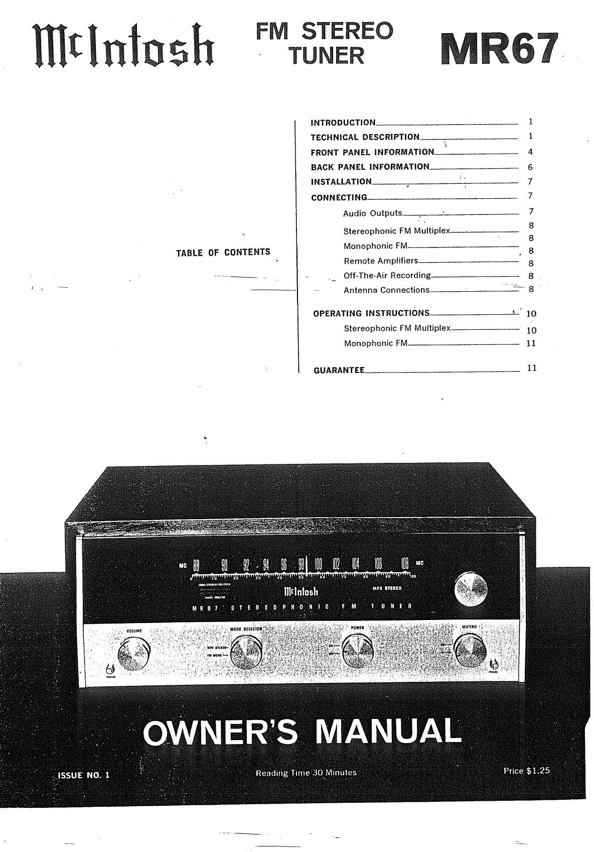
McIntosh MR 67 Owners Manual

This is the 14 pages manual for McIntosh MR 67 Owners Manual.
Read or download the pdf for free. If you want to contribute, please mail your pdfs to info@audioservicemanuals.com.

Page: 1 / 14
left right
McIntosh MR 67 Owners Manual

Extracted text from McIntosh MR 67 Owners Manual (Ocr-read)


Page 1

t ntush .FMTSLEE'EEO MR6?

INTRODUCTION-
TECHNICAL DESCRIPTION 7'
FRONT PANEL INFORMATION ;
BACK PANEL INFORMATION
INSTALLATION
CONNECTING

Audio Outputs

Stereophnnic FM Multiplex

Monophonic FM

mmmmmmuwvmppw

TABLE OF CONTENTS
Remote Amplifiers

M « A Oil-TheAir Recording

Antenna Conneclions

OPERATING INSTRUCTIONS#__._.L 10
Stereophunic FM MultiplexF.- 10
Monophonic FM_------- 11

GUARANTEE 11

mllnlush mm mum '
Mas] BIEEVIUPJIDVIIIO I'M IUNER

mum

ISSUE N04 > F_ V ' Price$1.25

Page 2

1'

MR67 FM STEREO TUNER

INTRODUCTION

The McIntosh MR67 isa precision engi-
neered, highly sensitive FM Multiplex Tuner.

The finest possible reception of FM mono-
phonic and FM multiplex stereophonic broad-
casts is assured by another McIntosh first-
a built-in MULTIPATH INDICATOR. Multipath
reception of FM transmissions causes noisy
and distorted sounding programs.

Multipath distortion is caused by receiving
both a direct signal and one or more reflected
signals. Multipath signals may be reflected

from a building, watertower or even a nearby .

hill or mountain. The multipath reflected sig-

-= Inals reach the antenna at slightly later times

than the direct signals due to the longer dis-
tances they travel. The time differences of
the direct and multipath signals at the an-
tenna can cause moderate or severe distor-
tion at the tuner outputs. Multipath can be
eliminated or greatly reduced by proper-use

ofa directional antenna. The MR67 multipath

indicator shows when the antenna is rotated
to the correct position for picking up only the
desired direct signal.

The MR67 also uses the new, exclusive
Mélntosh PANLOC method of installation.
The PANLOC system gives you absolute ease
of installation, operation, and maintenance.

PANLOC is the first professional installation
technique to be used on stereo instruments.

In the PANLOC system a metal shelf is
mounted first then the tuner slides into
position on this shelf. Depressing the PAN-
LOC buttons on the front panel locks the
tuner firmly into place for normal operation.
To unlock the tuner depress a second time
the PANLOC buttons on the front panel. The
tuner can now slide forward to the ADJUST"
position. The tuner will lock into thisposition
approximately 3 inches from the mounting
panel Now you can adjust the multipath-
signal strength indicator switch and the panel
light switch, both of Which are mounted just
behind the front panel. Depressing the AD-
JUST position holding latches allows the
tuner to be taken out of the PANLOC shelf or
to slide back into position against the mount-

, ingpanel.

Once you have enjoyed the outstanding
performance of the MR67. you will under-
stand why McIntosh products have earned
their reputation as THE BEST." Your Mcln-
tosh MR67 tuner will give you years of the
finest possible FM reception, and will become
a highly valued part of your home music
system.

TECHNICAL DESCRIPTION

The MR67 tuner has a 6084 highegain
Nuvistor for the first RF amplifier stage. The
Nuvistor (triode) operates into a triode tube
to form a cascode amplifier. Careful design
of the operating characteristics allows the
cascode amplifier to handle a wide dynamic
range of signals with excellent signal-tonoise
ratio. Proper design of circuit constants.
together with extreme care in manufacturing,
reduces spurious signals to a minimum.
Sensitivity is increased to the highest pos-
sible degree, while still retaining high selec-
tivity. A low-noise triode mixer follows the
RF stages.

The high frequency oscillator mechanical
construction and layout are engineered for

minimum responses to temperature varia
tions. The combination of both mechanical
and electronic design in the MR67 oscillator
circuit is so precise that a compensating
automatic frequency control is not needed.

The mixer output is amplified through four
intermediate frequency stages with flat-
topped highly selective response curves. The
IF transformers are designed for wide band
response with maximum adjacent channel
rejection. Construction of the lFtransformers
assures electrical stability and resistance to
mechanical shock and vibration.

Two limiter stages are used followed by a
wide-band discriminator. The second limiter
is part of the muting circuit which automat-